
13.3: Influence Lines for Statically Indeterminate Beams by Kinematic Method
- Page ID
- 43007

In 1886, Heinrich Muller-Breslau, a German Professor, developed a procedure for the establishment of the shape of the influence lines for functions such as reactions, shears, moments, and axial forces in members without any computational effort. The influence lines obtained by this method are also referred to as qualitative influence lines, as there is no calculation involved. The Muller-Breslau method is based on the principle of virtual work. The procedure for this method, which is commonly referred to as Muller-Breslau’s principle, is stated as follows:
The influence line for any function such as a reaction, shear, or moment of a structure can be represented by the deflected shape of a release structure obtained by removing from the given structure the restraint that corresponds to the particular function being considered, and then introducing a unit displacement or rotation in the direction and the location of the function being considered.
When there is a need to obtain the ordinates for the influence lines while using the kinematic method, this procedure must be complemented by other analytical techniques, such as the method of singularity function, the Hardy Cross method of moment distribution, the energy methods, and the conjugate beam principle. In such instances, the procedure is as follows:
Procedure for Analysis of Influence Lines by the Kinematic Method
•Obtain the released structure by removing the restraint that corresponds to the function whose influence line is desired.
•Apply a unit displacement or rotation to the released structure in the direction and at the location of the function whose influence line is desired.
•Draw the deflected shape of the released structure. This corresponds to the influence line of the function being considered.
•Place a unit load at the location and in the direction of the function being considered, and find the value of the ordinate of the influence line using statics.
•Using geometry, determine the value of other ordinates of influence using geometry.
Example 13.3
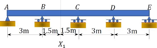
Using the Muller-Breslau’s principle, draw the qualitative influence lines for the vertical reactions at supports \(A\), \(B\), and \(C\), the shear and bending moment at section \(X_{1}\), and the bending moment at support \(D\) of the five-span beam shown in Figure 13.4a.
Solution
Qualitative influence line for the vertical reactions at support \(A\), \(B\), and \(C\).
To draw the qualitative influence line for \(A_{y}\), first obtain the release structure by removing the support at \(A\). Applying a unit displacement at point \(A\) in the release structure, in the positive direction of \(A_{y}\), will result in the deflected shape shown in Figure 13.4b. The resulting deflected shape represents the shape of the influence line of \(A_{y}\). To obtain the shape of the influence lines for \(B_{y}\) and \(C_{y}\), similar procedures are followed and will yield the deflected shapes shown in Figure13.4c and Figure13.4d.
Qualitative influence lines for the shear at section \(X_{1}\).
The qualitative influence line for the shear at section \(X_{1}\) is drawn by first breaking the beam at the section and then applying two vertical forces in a manner that will cause a positive shear on the left and the right portion of the break. The resulting deflected shape is shown in Figure 13.4e.
Qualitative influence lines for the bending moment at section \(X_{1}\).
The influence line of the moment at section \(X_{1}\) is found by first inserting an imaginary hinge at the section \(X_{1}\) and then applying a pair of positive bending moments adjacent to both sides of the hinge. The resulting deflected shape shown in Figure 13.4f represents the shape of the qualitative influence line for the bending moment at the section.
Qualitative influence lines for the bending moment at support \(D\).
The influence line for the moment at the support \(D\) is obtained by first releasing the restrain at the support, inserting a pin at point \(D\) of the release structure, and then applying a pair of moments adjacent to both sides of the hinge in the positive direction of \(M_{D}\). The resulting deflected shape shown in Figure 13.4g represents the shape of the qualitative influence line for the bending moment at the section.
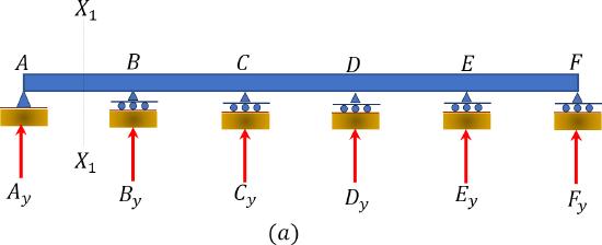
\(Fig. 13.4\). Five – span beam.
Chapter Summary
Influence lines for indeterminate structures: The procedure for the construction of influence lines for indeterminate structures by the equilibrium method and the Muller-Breslau principle were discussed, and a few example problems were solved in this chapter. Unlike the influence lines for determinate structures, which are straight lines, the influence line for indeterminate structures are curvilinear.
Practice Problems
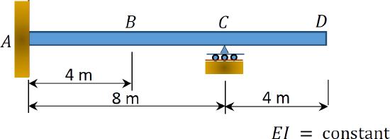
13.1 Using the equilibrium method, draw the influence lines for the vertical reactions at \(ACD\) of the beam shown in Figure P13.1. Also, draw the influence line for the shear force and bending moment at a section at \(B\) of the beam.
\(Fig. P 13.1\). Beam.
13.2 Using the equilibrium method, draw the influence lines for the vertical reactions at the supports of the indeterminate beam with overhanging ends, as shown in Figure P13.2.
\(Fig. P 13.2\). Indeterminate beam.
13.3 Using the equilibrium method, draw the influence lines for the vertical reactions at supports \(A\) and \(C\) of the propped cantilever beam shown in Figure P13.3.
\(Fig. P 13.3\). Propped cantilever beam.
13.4 Using Muller-Breslau’s principle, draw the qualitative influence lines for the vertical reactions at supports \(A\), \(B\), and \(C\), positive shear and moment at section \(X_{1}\).
\(Fig. P13.4\). Beam.
13.5 Using Muller-Breslau’s principle, draw the qualitative influence lines for the vertical reactions at supports \(E\) and \(F\), the negative moment at \(C\), negative shear and moment at section \(X_{1}\).
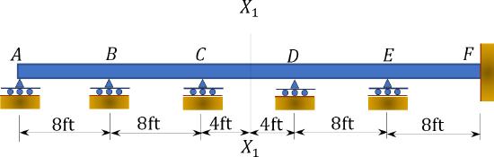
\(Fig. P13.5\) Beam.
13.6 Using Muller-Breslau’s principle, draw the qualitative influence lines for the maximum vertical reactions at supports \(A\) and \(B\), maximum negative shear and moment at section \(X_{1}\).
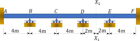
\(Fig. P13.6\). Beam.