

5.7: Chapter Homework Problems
- Page ID
- 111340

\( \newcommand{\vecs}[1]{\overset { \scriptstyle \rightharpoonup} {\mathbf{#1}} } \)
\( \newcommand{\vecd}[1]{\overset{-\!-\!\rightharpoonup}{\vphantom{a}\smash {#1}}} \)
\( \newcommand{\dsum}{\displaystyle\sum\limits} \)
\( \newcommand{\dint}{\displaystyle\int\limits} \)
\( \newcommand{\dlim}{\displaystyle\lim\limits} \)
\( \newcommand{\id}{\mathrm{id}}\) \( \newcommand{\Span}{\mathrm{span}}\)
( \newcommand{\kernel}{\mathrm{null}\,}\) \( \newcommand{\range}{\mathrm{range}\,}\)
\( \newcommand{\RealPart}{\mathrm{Re}}\) \( \newcommand{\ImaginaryPart}{\mathrm{Im}}\)
\( \newcommand{\Argument}{\mathrm{Arg}}\) \( \newcommand{\norm}[1]{\| #1 \|}\)
\( \newcommand{\inner}[2]{\langle #1, #2 \rangle}\)
\( \newcommand{\Span}{\mathrm{span}}\)
\( \newcommand{\id}{\mathrm{id}}\)
\( \newcommand{\Span}{\mathrm{span}}\)
\( \newcommand{\kernel}{\mathrm{null}\,}\)
\( \newcommand{\range}{\mathrm{range}\,}\)
\( \newcommand{\RealPart}{\mathrm{Re}}\)
\( \newcommand{\ImaginaryPart}{\mathrm{Im}}\)
\( \newcommand{\Argument}{\mathrm{Arg}}\)
\( \newcommand{\norm}[1]{\| #1 \|}\)
\( \newcommand{\inner}[2]{\langle #1, #2 \rangle}\)
\( \newcommand{\Span}{\mathrm{span}}\) \( \newcommand{\AA}{\unicode[.8,0]{x212B}}\)
\( \newcommand{\vectorA}[1]{\vec{#1}} % arrow\)
\( \newcommand{\vectorAt}[1]{\vec{\text{#1}}} % arrow\)
\( \newcommand{\vectorB}[1]{\overset { \scriptstyle \rightharpoonup} {\mathbf{#1}} } \)
\( \newcommand{\vectorC}[1]{\textbf{#1}} \)
\( \newcommand{\vectorD}[1]{\overrightarrow{#1}} \)
\( \newcommand{\vectorDt}[1]{\overrightarrow{\text{#1}}} \)
\( \newcommand{\vectE}[1]{\overset{-\!-\!\rightharpoonup}{\vphantom{a}\smash{\mathbf {#1}}}} \)
\( \newcommand{\vecs}[1]{\overset { \scriptstyle \rightharpoonup} {\mathbf{#1}} } \)
\(\newcommand{\longvect}{\overrightarrow}\)
\( \newcommand{\vecd}[1]{\overset{-\!-\!\rightharpoonup}{\vphantom{a}\smash {#1}}} \)
\(\newcommand{\ket}[1]{\left| #1 \right>}\)
\(\newcommand{\bra}[1]{\left< #1 \right|}\)
\(\newcommand{\braket}[2]{\left< #1 \vphantom{#2} \right| \left. #2 \vphantom{#1} \right>}\)
\(\newcommand{\braopket}[3]{\left< #1 \vphantom{#2}\vphantom{#3} \right| #2 \vphantom{#1}\vphantom{#3} \left| #3 \vphantom{#1}\vphantom{#2} \right>}\)
\(\newcommand{\qmvec}[1]{\mathbf{\vec{#1}}}\)
\(\newcommand{\op}[1]{\hat{\mathbf{#1}}}\)
\(\newcommand{\expect}[1]{\langle #1 \rangle}\)
\(\newcommand{\dfn}[1]{\emph{\textbf{#1}}}\)
Exercise \(\PageIndex{1}\)
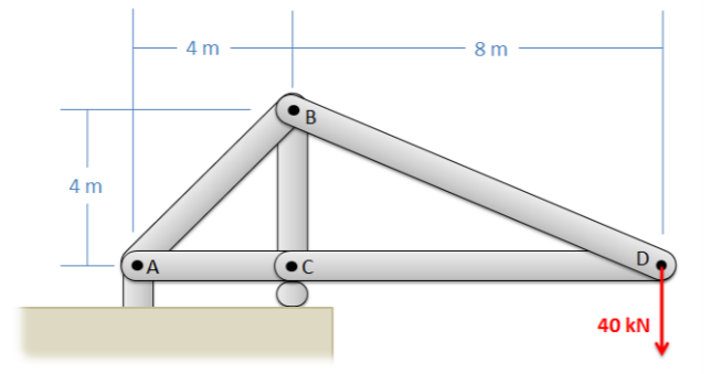
Use the method of joints to solve for the forces in each member of the lifting gantry truss shown below.
- Solution
-
\(F_{AB} = 113.14\) kN T, \(F_{AC} = 80\) kN C, \(F_{BC} = 120\) kN C
\(F_{BD} = 89.44\) kN T, \(F_{CD} = 80\) kN C
Exercise \(\PageIndex{2}\)
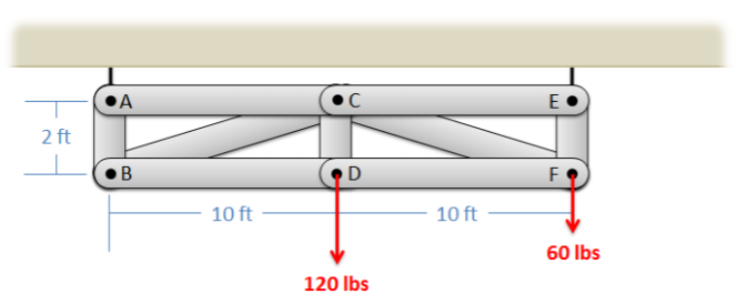
The truss shown below is supported by two cables at A and E, and supports two lighting rigs at D and F, as shown by the loads. Use the method of joints to determine the forces in each of the members.
- Solution
-
\(F_{AB} = 60\) lbs T, \(F_{AC} = 0\), \(F_{BC} = 305.94\) lbs C
\(F_{BD} = 300\) lbs T, \(F_{CD} = 120\) lbs T, \(F_{CE} = 0\)
\(F_{CF} = 305.94\) lbs C, \(F_{DF} = 300\) lbs T, \(F_{EF} = 120\) lbs T
Exercise \(\PageIndex{3}\)
The truss shown below is supported by a pin joint at A, a cable at D, and is supporting a 600 N load at point C. Use the method of joints to determine the forces in each of the members. Assume the mass of the beams are negligible.

- Solution
-
\(F_{AB} = 1162.97\) N C, \(F_{AC} = 709.86\) N T, \(F_{BC} = 0\)
\(F_{BD} = 1162.97\) N C, \(F_{CD} = 709.86\) N T
Exercise \(\PageIndex{4}\)
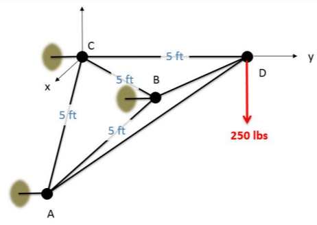
The space truss shown below is being used to lift a 250 lb box. The truss is anchored by a ball-and-socket joint at C (which can exert reaction forces in the \(x\), \(y\), and \(z\) directions) and supports at A and B that only exert reaction forces in the y direction. Use the method of joints to determine the forces acting all members of the truss.
- Solution
-
\(F_{AB} = 0\), \(F_{AC} = 144.33\) lbs T, \(F_{AD} = 204.09\) lbs C
\(F_{BC} = 144.33\) lbs T, \(F_{BD} = 204.09\) lbs C, \(F_{CD} = 288.68\) lbs T
Exercise \(\PageIndex{5}\)
Use the method of sections to solve for the forces acting on members CE, CF, and DF of the gantry truss shown below.
- Solution
-
\(F_{CE} = 0\), \(F_{CF} = 306.2\) lbs C, \(F_{DF} = 300.2\) lbs T
Exercise \(\PageIndex{6}\)
You are asked to compare two crane truss designs as shown below. Find the forces in members AB, BC, and CD for Design 1 and find forces AB, AD, and CD for Design 2. What member is subjected to the highest loads in either case?

- Solution
-
Design 1: \(F_{AB} = 11,276\) lbs T, \(F_{BC} = 2902\) lbs T, \(F_{CD} = 18,967\) lbs C
Design 2: \(F_{AB} = 13,322\) lbs T, \(F_{AD} = 2902\) lbs C, \(F_{CD} = 16,914\) lbs C
The largest forces are in member CD for both designs.
Exercise \(\PageIndex{7}\)
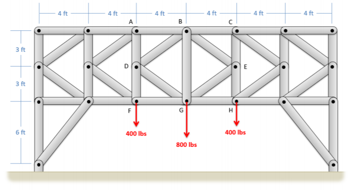
The K truss shown below supports three loads. Assume only vertical reaction forces at the supports. Use the method of sections to determine the forces in members AB and FG. (Hint: you will need to cut through more than three members, but you can use your moment equations strategically to solve for exactly what you need).
- Solution
-
\(F_{AB} = 1066.67\) lbs C, \(F_{FG} = 1066.67\) lbs T
Exercise \(\PageIndex{8}\)
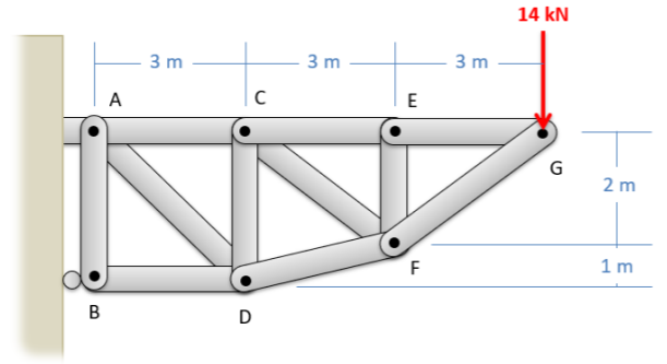
The truss shown below is supported by a pin support at A and a roller support at B. Use the hybrid method of sections and joints to determine the forces in members CE, CF, and CD.
- Solution
-
\(F_{CE} = 21\) kN T, \(F_{CF} = 8.41\) kN T, \(F_{CD} = 4.67\) kN C
Exercise \(\PageIndex{9}\)
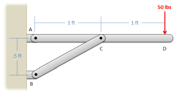
The shelf shown below is used to support a 50-lb weight. Determine the forces on members ACD and BC in the structure. Draw those forces on diagrams of each member.
- Solution
-
\(F_{BC} = 223.6\) lbs (Compression), \(F_{A_X} = -200\) lbs, \(F_{A_Y} = -50\) lbs
Exercise \(\PageIndex{10}\)
A 20 N force is applied to a can-crushing mechanism as shown below. If the distance between points C and D is 0.1 meters, what are the forces being applied to the can at points B and D? (Hint: treat the can as a two-force member)

- Solution
-
\(F_{can} = 148.9\) N (Compression)
Exercise \(\PageIndex{11}\)
The suspension system on a car is shown below. Assuming the wheel is supporting a load of 3300 N and assuming the system is in equilibrium, what is the force we would expect in the shock absorber (member AE)? You can assume all connections are pin joints.

- Solution
-
\(F_{AE} = 4611.9\) N (Compression)
Exercise \(\PageIndex{12}\)
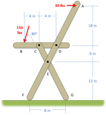
The chair shown below is subjected to forces at A and B by a person sitting in the chair. Assuming that normal forces exist at F and G, and that friction forces only act at point G (not at F), determine all the forces acting on each of the three members in the chair. Draw these forces acting on each part of the chair on a diagram.
- Solution
-
\(F_F = 108.3\) lbs, \(F_{G_X} = -3.95\) lbs, \(F_{G_Y} = 39.5\) lbs
\(F_{C_X} = \pm \, 16.89\) lbs, \(F_{C_Y} = \pm \, 295.4\) lbs
\(F_{D_X} = \pm \, 142.9\) lbs, \(F_{D_Y} = \pm \, 147.7\) lbs
\(F_{E_X} = \pm \, 112.9\) lbs, \(F_{E_Y} = \pm \, 256.0\) lbs