Engineering LibreTexts

2.2: Point Forces as Vectors

  • Page ID
    50573
  • \( \newcommand{\vecs}[1]{\overset { \scriptstyle \rightharpoonup} {\mathbf{#1}} } \) \( \newcommand{\vecd}[1]{\overset{-\!-\!\rightharpoonup}{\vphantom{a}\smash {#1}}} \)\(\newcommand{\id}{\mathrm{id}}\) \( \newcommand{\Span}{\mathrm{span}}\) \( \newcommand{\kernel}{\mathrm{null}\,}\) \( \newcommand{\range}{\mathrm{range}\,}\) \( \newcommand{\RealPart}{\mathrm{Re}}\) \( \newcommand{\ImaginaryPart}{\mathrm{Im}}\) \( \newcommand{\Argument}{\mathrm{Arg}}\) \( \newcommand{\norm}[1]{\| #1 \|}\) \( \newcommand{\inner}[2]{\langle #1, #2 \rangle}\) \( \newcommand{\Span}{\mathrm{span}}\) \(\newcommand{\id}{\mathrm{id}}\) \( \newcommand{\Span}{\mathrm{span}}\) \( \newcommand{\kernel}{\mathrm{null}\,}\) \( \newcommand{\range}{\mathrm{range}\,}\) \( \newcommand{\RealPart}{\mathrm{Re}}\) \( \newcommand{\ImaginaryPart}{\mathrm{Im}}\) \( \newcommand{\Argument}{\mathrm{Arg}}\) \( \newcommand{\norm}[1]{\| #1 \|}\) \( \newcommand{\inner}[2]{\langle #1, #2 \rangle}\) \( \newcommand{\Span}{\mathrm{span}}\)\(\newcommand{\AA}{\unicode[.8,0]{x212B}}\)

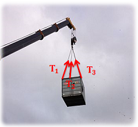
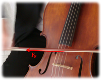
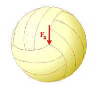
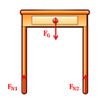
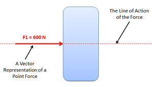
    A point force is any force where the point of application is considered to be a single point. In reality, most forces are technically surface forces, where the force is applied over an area, but when the area is small enough (in comparison to the bodies being analyzed) it can often be approximated as a point force. Because point forces can be represented as a single vector (rather than a field of vectors for distributed forces), they are much easier to work with in engineering analysis. For this reason, point forces are used in place of distributed forces in engineering analysis whenever possible. Below are some examples of where it is appropriate to use point forces.

    A shipping container held up by 3 cables attached to a crane, with the 3 tension forces of the cables on the container illustrated as point forces.
    Figure \(\PageIndex{1}\): The tensions in the cables supporting this container can be treated as point forces pulling in the direction of the cables. Adapted from Image by maxronnersjo CC-BY-SA 3.0.
    A cello being played with a bow, with the friction force of the bow on the strings illustrated as a point force.
    Figure \(\PageIndex{2}\): The friction force between the bow and string on this cello can be treated as a point force. Adapted from Public Domain image by Levi.
    A volleyball with the gravitational force acting on its center of gravity illustrated.
    Figure \(\PageIndex{3}\): Though gravitational forces are technically body forces, they are often approximated as a single point force acting on the center of gravity of the object. Adapted from Public Domain image, no author listed.
    A two-legged table with the contact force on each leg and the gravitational force on the table's center of mass illustrated as point forces.
    Figure \(\PageIndex{4}\): The gravitational force and the normal forces acting on each leg of this table can all be approximated as point forces. Adapted from Public Domain image by Seahen.

    In addition to the magnitude, direction, and point of application of the point force, another important term to understand is the line of action of the force. The line of action of a force is the line along which the force acts. Given the direction and point of application, one can find the line of action, but this term will be important in discussing concurrent forces and in the principle of transmissibility.

    An oblong shape with a vector representation of a point force acting horizontally on it, with the line of action along that vector also shown.
    Figure \(\PageIndex{5}\): The line of action of a point force is the line along which the force acts.

    Force Vector Representation:

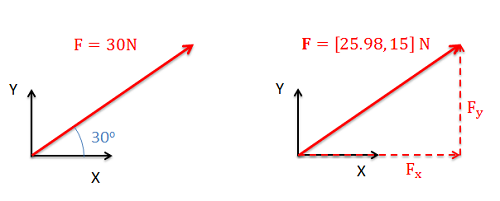
    When vectors are drawn to form free body diagrams, the magnitude and direction are usually given in one of two formats:

    • Overall magnitude and angle(s) to indicate direction (often called magnitude and direction form).
    • Magnitudes in each of the coordinate directions (often called component form).

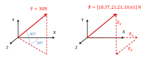
    In either format we will need two values to fully define a force vector in a 2D system (either a magnitude and a single angle or a magnitude in each of the two coordinate axes), and three values to fully define a force vector in a 3D system (either a magnitude and two angles or a magnitude in each of the three coordinate axes). Below are some examples of force vectors in both representations.

    The same two-dimensional force vector is represented in terms of its magnitude and angle to the x-axis on the left, and in terms of its x and y components on the right.
    Figure \(\PageIndex{6}\): The same force can be represented with a magnitude and an angle, as shown in the left, or with magnitudes in relation to each of the coordinate axes as shown on the right.
    The same three-dimensional force vector is represented in terms of its magnitude and angle to the x and y axes on the left, and in terms of its x, y and z components on the right.
    Figure \(\PageIndex{7}\): In three dimensions forces are represented with either a magnitude and two directions, as shown on the left, or with magnitudes in relation to each of the three coordinate axes as shown on the right.

    Changing Force Vector Forms:

    Because the two different forms of the vector are equivalent, we can switch between representations without changing the problem. Often in engineering problems, it will initially be easier to write the force in magnitude and angle form, but later, analysis will be easier if forces are written in component form. To switch from magnitude and direction form to component form you will use right triangles and trigonometry to determine the component of the overall magnitude in each direction. This is a simple vector decomposition, and more information on this process can be seen on the vector decomposition page. To switch back from component form into magnitude and direction form you simply use the reverse of this initial process.

    Video lecture covering this section, delivered by Dr. Jacob Moore. YouTube source: https://youtu.be/kq8vqOKhKeA.

    Example \(\PageIndex{1}\)

    The tension force on the box below is given in magnitude and direction form. Redraw the diagram with the tension force given in component form.

    A box with a tension force of magnitude 60 Newtons applied to it, pulling up and to the right at 15 degrees above the horizontal.

    Solution
    Video \(\PageIndex{2}\): Worked solution to example problem \(\PageIndex{1}\), provided by Dr. Jacob Moore. YouTube source: https://youtu.be/ZERURXWnlDg.

    Example \(\PageIndex{2}\)

    The force acting on the cantilever beam shown below is given in component form. Redraw the diagram with the force given in magnitude and direction form.

    A cantilever beam attached to a wall, with a force with the components [-300, -250] N being applied to the free end.

    Solution
    Video \(\PageIndex{3}\): Worked solution to example problem \(\PageIndex{2}\), provided by Dr. Jacob Moore. YouTube source: https://youtu.be/M3UjDfZzRHY.

    Example \(\PageIndex{3}\)

    The force shown below is given in magnitude and direction form. Redraw the diagram with the force vector given in component form.

    A force vector, magnitude 30 N, drawn on a three-dimensional coordinate plane, pointing up and to the right with its tail at the origin. The vector is 45 degrees above the xz plane, and its projection onto the xz plane makes a 30 degree angle with the x axis.

    Solution
    Video \(\PageIndex{4}\): Worked solution to example problem \(\PageIndex{3}\), delivered by Dr. Jacob Moore. YouTube source: https://youtu.be/DroNv0TxnyA.

    This page titled 2.2: Point Forces as Vectors is shared under a CC BY-SA 4.0 license and was authored, remixed, and/or curated by Jacob Moore & Contributors (Mechanics Map) via source content that was edited to the style and standards of the LibreTexts platform; a detailed edit history is available upon request.