
4.6: Chapter 4 Homework Problems
- Page ID
- 52472

Exercise \(\PageIndex{1}\)
Determine if the two systems below are statically equivalent.
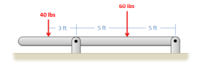.png?revision=1)
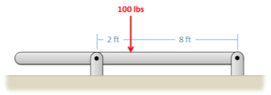.png?revision=1)
- Solution
-
No, they are not equivalent.
Exercise \(\PageIndex{2}\)
Determine if the set of forces in A is statically equivalent to the set of forces and moments in B.
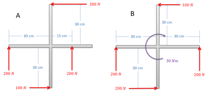.png?revision=1)
- Solution
-
No, they are not equivalent.
Exercise \(\PageIndex{3}\)
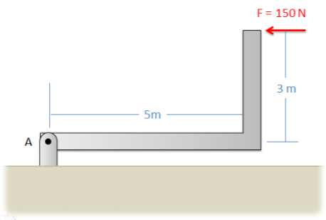
Resolve the force shown below into a force and a couple acting at point A. Draw this force and couple on a diagram of the L-shaped beam.
.png?revision=1)
- Solution
-
\(F_A = 150 \, N\) to the left
\(M_A = 450 \, Nm\)
Exercise \(\PageIndex{4}\)
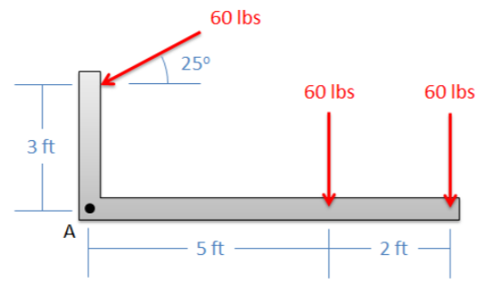
Find the equivalent force couple system acting at point A for the setup shown below. Draw this force and couple on a diagram of the L-shaped beam.
.png?revision=1)
- Solution
-
\(F_A = 155.2 \, lbs, \, 69.5\)° below the negative \(x\)-axis
\(M_A = -556.9 \, ft \, lbs\)
Exercise \(\PageIndex{5}\)
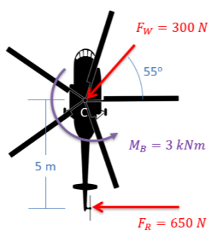
A helicopter is hovering with the wind force, the force from the tail rotor, and the moment due to drag shown below. Determine the equivalent force couple system at point C. Draw the final force and moment on a new diagram of the helicopter.
.png?revision=1)
- Solution
-
\(F_{eq} = 858.01 \, N\) acting at \(16.6\)° below the negative \(x\)-axis
\(M_{eq} = -250 \, N \, m\)
Exercise \(\PageIndex{6}\)
Determine the equivalent point load (magnitude and location) for the distributed force shown below, using integration.
.png?revision=1)
- Solution
-
\(F_{eq} = 105 \, N\)
\(x_{eq} = 3.29 \, m\) (measured from wall)
Exercise \(\PageIndex{7}\)
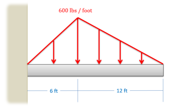
Determine the equivalent point load (magnitude and location) for the distributed force shown below, using integration.
.png?revision=1)
- Solution
-
\(F_{eq} = 5400 \, lbs\)
\(x_{eq} = 8 \, ft\) (measured from wall)
Exercise \(\PageIndex{8}\)
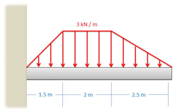
Use the method of composite parts to determine the magnitude and location of the equivalent point load for the distributed force shown below.
.png?revision=1)
- Solution
-
\(F_{eq} = 12 \, kN\)
\(x_{eq} = 2.79 \, m\) (measured from wall)