
5.5: Method of Sections
- Page ID
- 52781

The method of sections is a process used to solve for the unknown forces acting on members of a truss. The method involves breaking the truss down into individual sections and analyzing each section as a separate rigid body. The method of sections is usually the fastest and easiest way to determine the unknown forces acting in a specific member of the truss.
Using the Method of Sections:
The process used in the method of sections is outlined below.
- In the beginning, it is usually useful to label the members in your truss. This will help you keep everything organized and consistent in later analysis. In this book, the members will be labeled with letters.
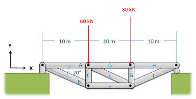
Figure \(\PageIndex{1}\): The first step in the method of sections is to label each member.
- Treating the entire truss structure as a rigid body, draw a free body diagram, write out the equilibrium equations, and solve for the external reacting forces acting on the truss structure. This analysis should not differ from the analysis of a single rigid body.
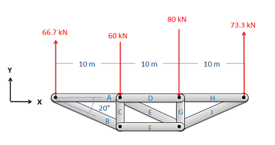
Figure \(\PageIndex{2}\): Treat the entire truss as a rigid body and solve for the reaction forces supporting the truss structure.
- Next, you will imagine cutting your truss into two separate sections. The cut should travel through the member that you are trying to solve for the forces in, and should cut through as few members as possible. The cut does not need to be a straight line.
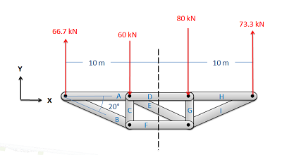 Figure \(\PageIndex{3}\): Next you will imagine cutting the truss into two parts. If you want to find the forces in a specific member, be sure to cut through that member. It also makes things easier if you cut through as few members as possible.
- Next, you will draw a free body diagram for either one or both sections that you created. Be sure to include all the forces acting on each section.
- Any external reaction or load forces that may be acting at the section.
- An internal force in each member that was cut when splitting the truss into sections. Remember that for a two-force member, the force will be acting along the line between the two connection points on the member. We will also need to guess if it will be a tensile or a compressive force. An incorrect guess now, though, will simply lead to a negative solution later on. A common strategy then is to assume all forces are tensile; then later in the solution any positive forces will be tensile forces and any negative forces will be compressive forces.
- Label each force in the diagram. Include any known magnitudes and directions and provide variable names for each unknown.
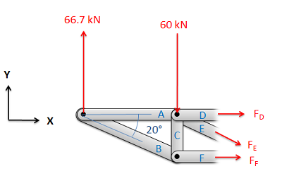
Figure \(\PageIndex{4}\): Next, draw a free body diagram of one or both halves of the truss. Add the known forces, as well as unknown tensile forces for each member that you cut.
- Write out the equilibrium equations for each section you drew a free body diagram of. These will be extended bodies, so you will need to write out the force and the moment equations.
- For 2D problems you will have three possible equations for each section: two force equations and one moment equation. \[ \sum \vec{F} = 0 \quad\quad\quad\quad \sum \vec{M} = 0 \] \[ \sum F_x = 0 \, ; \,\,\, \sum F_y = 0 \, ; \,\,\, \sum M_z = 0 \]
- For 3D problems you will have six possible equations for each section: three force equations and three moment equations. \[ \sum \vec{F} = 0 \] \[ \sum F_x = 0 \, ; \,\,\, \sum F_y = 0 \, ; \,\,\, \sum F_z = 0 \] \[ \sum \vec{M} = 0 \] \[ \sum M_x = 0 \, ; \,\,\, \sum M_y = 0 \, ; \,\,\, \sum M_z = 0 \]
- Finally, solve the equilibrium equations for the unknowns. You can do this algebraically, solving for one variable at a time, or you can use matrix equations to solve for everything at once. If you assumed that all forces were tensile earlier, remember that negative answers indicate compressive forces in the members.
Example \(\PageIndex{1}\)
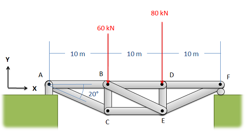
Find the forces acting on members BD and CE. Be sure to indicate if the forces are tensile or compressive.
- Solution
-
Video \(\PageIndex{2}\): Worked solution to example problem \(\PageIndex{1}\), provided by Dr. Jacob Moore. YouTube source: https://youtu.be/9xxmHpLB1uU.
Example \(\PageIndex{2}\)
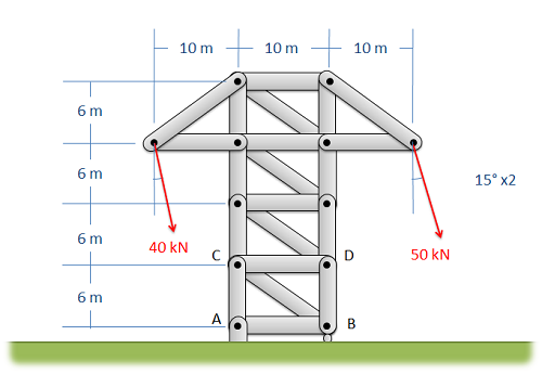
Find the forces acting on members AC, BC, and BD of the truss. Be sure to indicate if the forces are tensile or compressive.
- Solution
-
Video \(\PageIndex{3}\): Worked solution to example problem \(\PageIndex{2}\), provided by Dr. Jacob Moore. YouTube source: https://youtu.be/Kp9U4d2qbvE.