
5.7: Analysis of Frames and Machines
- Page ID
- 53662

The process used to analyze frames and machines involves breaking the structure down into individual components in order to solve for the forces acting on each component. Sometimes the structure as a whole can be analyzed as a rigid body, and each component can always be analyzed as a rigid body.
The Process for Analyzing Frames and Machines:
- In the beginning it is usually useful to label the members in your structure. This will help you keep everything organized and consistent in later analysis. In this book, we will label everything by assigning letters to each of the joints.
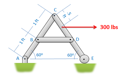 Figure \(\PageIndex{1}\): The first step in the analysis of frames and machines is to label the members.
- Next you will need to determine if we can analyze the entire structure as a rigid body. In order to do this, the structure needs to be independently rigid. This means that it would be rigid even if we separated it from its supports. If the structure is independently rigid (no machines, and only some frames, will be independently rigid), then analyze the structure as a single rigid body to determine the reaction forces acting on the structure. If the structure is not independently rigid, skip this step.
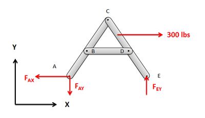
Figure \(\PageIndex{2}\): If, and only if, the structure is independently rigid, you should analyze the whole structure as a single rigid body to solve for the reaction forces.
- Next you will draw a free body diagram for each of the components in the structure. You will need to include all forces acting on each member:
- First, add any external reaction or load forces that may be acting on the components.
- Second, identify any two-force members in the structure. At their connection points, they will cause a force with an unknown magnitude but a known direction (the forces will act along the line between the two connection points on the member).
- Next, add in the reaction forces (and possibly moments) at the connection points between non-two-force members. For forces with an unknown magnitude and direction (such as in pin joints), the forces are often drawn in as having unknown \(x\) and \(y\) components (\(x\), \(y\) and \(z\) for 3D truss problems).
- Remember that the forces at each of the connection points will be a Newton's Third Law pair. This means that if one member exerts some force on some other member, then the second member will exert an equal and opposite force back on the first. When we draw out our unknown forces at the connection points, we must make sure that the forces acting on each member are opposite in direction.
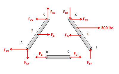 Figure \(\PageIndex{3}\): Separate the structure into individual components and draw a free body diagram of each component. It is important to remember that the forces at each connection point are a Newton's Third Law pair.
- Write out the equilibrium equations for each component you drew a free body diagram of. These will be extended bodies, so you will need to write out the force and the moment equations.
- For 2D problems you will have three possible equations for each section: two force equations and one moment equation. \[ \sum \vec{F} = 0 \quad\quad\quad\quad \sum \vec{M} = 0 \] \[ \sum F_x = 0 \, ; \,\,\, \sum F_y = 0 \, ; \,\,\, \sum M_z = 0 \]
- For 3D problems you will have six possible equations for each section: three force equations and three moment equations. \[ \sum \vec{F} = 0 \] \[ \sum F_x = 0 \, ; \,\,\, \sum F_y = 0 \, ; \,\,\, \sum F_z = 0 \] \[ \sum \vec{M} = 0 \] \[ \sum M_x = 0 \, ; \,\,\, \sum M_y = 0 \, ; \,\,\, \sum M_z = 0 \]
- Finally, solve the equilibrium equations for the unknowns. You can do this algebraically, solving for one variable at a time, or you can use matrix equations to solve for everything at once. If any force turns out to be negative, that indicates that the force actually travels in the opposite direction from what is indicated in your initial free body diagram.
Example \(\PageIndex{1}\)
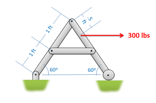
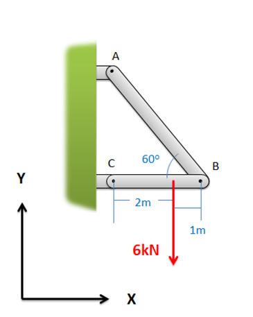
Find all the forces acting on each of the members in the structure below.
- Solution
-
Video \(\PageIndex{2}\): Worked solution to example problem \(\PageIndex{1}\), provided by Dr. Jacob Moore. YouTube source: https://youtu.be/ix2BuRGMGBs.
Example \(\PageIndex{2}\)
Find all the forces acting on each of the members in the structure below.
- Solution
-
Video \(\PageIndex{3}\): Worked solution to example problem \(\PageIndex{2}\), provided by Dr. Jacob Moore. YouTube source: https://youtu.be/TJjsz5Yt3Y0.
Example \(\PageIndex{3}\)
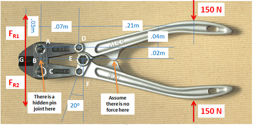
If two 150-Newton forces are exerted on the handles of the bolt cutter shown below, determine the reaction forces \((F_{R1}\) and \((F_{R2})\) exerted on the blades of the bolt cutter (this will be equal to the cutting forces exerted by the bolt cutters).
- Solution
-
Video \(\PageIndex{4}\): Worked solution to example problem \(\PageIndex{3}\), provided by Dr. Jacob Moore. YouTube source: https://youtu.be/uLsfSMzc5eQ.
Example \(\PageIndex{4}\)
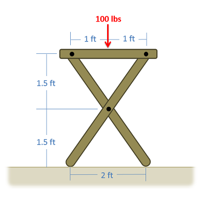
A 100-lb force is exerted on one side of a TV tray as shown below. Assuming there are no friction forces at the base, determine all forces acting on each of the three parts of the TV tray.
- Solution
-
Video \(\PageIndex{5}\): Worked solution to example problem \(\PageIndex{4}\), provided by Dr. Jacob Moore. YouTube source: https://youtu.be/qi7WNDSb43k.