Engineering LibreTexts

5.8: Chapter 5 Homework Problems

  • Page ID
    53663
  • \( \newcommand{\vecs}[1]{\overset { \scriptstyle \rightharpoonup} {\mathbf{#1}} } \) \( \newcommand{\vecd}[1]{\overset{-\!-\!\rightharpoonup}{\vphantom{a}\smash {#1}}} \)\(\newcommand{\id}{\mathrm{id}}\) \( \newcommand{\Span}{\mathrm{span}}\) \( \newcommand{\kernel}{\mathrm{null}\,}\) \( \newcommand{\range}{\mathrm{range}\,}\) \( \newcommand{\RealPart}{\mathrm{Re}}\) \( \newcommand{\ImaginaryPart}{\mathrm{Im}}\) \( \newcommand{\Argument}{\mathrm{Arg}}\) \( \newcommand{\norm}[1]{\| #1 \|}\) \( \newcommand{\inner}[2]{\langle #1, #2 \rangle}\) \( \newcommand{\Span}{\mathrm{span}}\) \(\newcommand{\id}{\mathrm{id}}\) \( \newcommand{\Span}{\mathrm{span}}\) \( \newcommand{\kernel}{\mathrm{null}\,}\) \( \newcommand{\range}{\mathrm{range}\,}\) \( \newcommand{\RealPart}{\mathrm{Re}}\) \( \newcommand{\ImaginaryPart}{\mathrm{Im}}\) \( \newcommand{\Argument}{\mathrm{Arg}}\) \( \newcommand{\norm}[1]{\| #1 \|}\) \( \newcommand{\inner}[2]{\langle #1, #2 \rangle}\) \( \newcommand{\Span}{\mathrm{span}}\)\(\newcommand{\AA}{\unicode[.8,0]{x212B}}\)

    Exercise \(\PageIndex{1}\)

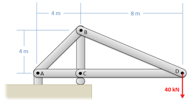
    Use the method of joints to solve for the forces in each member of the lifting gantry truss shown below.

    A structure composed of 5 members: a 4-meter horizontal member has its left end (point A) attached to the ground with a pin support and its right end (point C) attached to the the ground with a roller joint. A horizontal 8-meter member extends rightwards from point C, with a downwards 40-kN force applied on its unsupported right end (point D). A vertical 4-meter member extends upwards from point C, with its upper endpoint B connected to A and D by diagonal members.
    Figure \(\PageIndex{1}\): problem diagram for Exercise \(\PageIndex{1}\). A two-dimensional representation of a lifting gantry truss, which experiences a downwards force of 40 kN at one end.
    Solution

    \(F_{AB} = 113.14\) kN T, \(F_{AC} = 80\) kN C, \(F_{BC} = 120\) kN C

    \(F_{BD} = 89.44\) kN T, \(F_{CD} = 80\) kN C

    Exercise \(\PageIndex{2}\)

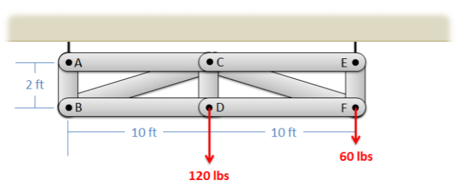
    The truss shown below is supported by two cables at A and E, and supports two lighting rigs at D and F, as shown by the loads. Use the method of joints to determine the forces in each of the members.

    A truss composed of 9 members: a horizontal 10-ft member is attached to the ceiling by a rigid support at its left end, A. At its right end, C, another horizontal 10-ft member extends rightwards with its free end (point E) also attached to the ceiling by a rigid support. A vertical 2-ft member extends downwards from each of these three points, forming members AB, CD, and EF. B, D and F are also connected by 2 10-ft horizontal members. One diagonal member connects B and C, and another connects C and F. A downwards force of 120 lbs is applied at D, and another of 60 lbs is applied at F.
    Figure \(\PageIndex{2}\): problem diagram for Exercise \(\PageIndex{2}\). A two-dimensional representation of a lighting support truss, which experiences the weights of lighting rigs hung at two points.
    Solution

    \(F_{AB} = 60\) lbs T, \(F_{AC} = 0\), \(F_{BC} = 305.94\) lbs C

    \(F_{BD} = 300\) lbs T, \(F_{CD} = 120\) lbs T, \(F_{CE} = 0\)

    \(F_{CF} = 305.94\) lbs C, \(F_{DF} = 300\) lbs T, \(F_{EF} = 120\) lbs T

    Exercise \(\PageIndex{3}\)

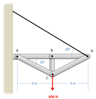
    The truss shown below is supported by a pin joint at A, a cable at D, and is supporting a 600 N load at point C. Use the method of joints to determine the forces in each of the members. Assume the mass of the beams are negligible.

    A truss consisting of 5 members: a horizontal 3-meter beam is attached to a wall at its left end, point A, by a pin joint. B, its right end is attached to another horizontal 3-meter beam whose right end, D, is supported by a cable leading to the wall that makes a 30° angle with the horizontal. A vertical beam extends downwards from B, with its lower end, point C, attached to A by a diagonal member making 25° angle with the horizontal. Another diagonal member connects C and D. A downwards 600-N force is applied at point C.
    Figure \(\PageIndex{3}\): problem diagram for Exercise \(\PageIndex{3}\). A two-dimensional representation of a truss connected to the wall at one end, supported by a cable at the other, and experiencing a downwards force at one point.
    Solution

    \(F_{AB} = 1162.97\) N C, \(F_{AC} = 709.86\) N T, \(F_{BC} = 0\)

    \(F_{BD} = 1162.97\) N C, \(F_{CD} = 709.86\) N T

    Exercise \(\PageIndex{4}\)

    The space truss shown below is being used to lift a 250 lb box. The truss is anchored by a ball-and-socket joint at C (which can exert reaction forces in the \(x\), \(y\), and \(z\) directions) and supports at A and B that only exert reaction forces in the y direction. Use the method of joints to determine the forces acting all members of the truss.

    A 3D coordinate plane with the x-axis pointing out of the screen, the y-axis pointing right in the plane of the screen, and the z-axis pointing upwards in the plane of the screen. On the "wall" of the xz plane an equilateral triangle of beams 5 feet long is attached as described above, oriented "point-up" with the upper vertex (C) at the origin, vertex A closer to the viewer, and B further into the screen. Point D, along the y-axis, is 5 feet to the right of C and is connected by members to points A, B, and C. A downwards force of 250 lbs is applied at point D.
    Figure \(\PageIndex{4}\): problem diagram for Exercise \(\PageIndex{4}\). A space truss attached to a wall at three points and supporting a load its free end.
    Solution

    \(F_{AB} = 0\), \(F_{AC} = 144.33\) lbs T, \(F_{AD} = 204.09\) lbs C

    \(F_{BC} = 144.33\) lbs T, \(F_{BD} = 204.09\) lbs C, \(F_{CD} = 288.68\) lbs T

    Exercise \(\PageIndex{5}\)

    Use the method of sections to solve for the forces acting on members CE, CF, and DF of the gantry truss shown below.

    A truss composed of 9 members: a horizontal 10-ft member is attached to the ceiling by a rigid support at its left end, A. At its right end, C, another horizontal 10-ft member extends rightwards with its free end (point E) also attached to the ceiling by a rigid support. A vertical 2-ft member extends downwards from each of these three points, forming members AB, CD, and EF. B, D and F are also connected by 2 10-ft horizontal members. One diagonal member connects B and C, and another connects C and F. A downwards force of 120 lbs is applied at D, and another of 60 lbs is applied at F.
    Figure \(\PageIndex{5}\): problem diagram for Exercise \(\PageIndex{5}\). A two-dimensional representation of a gantry truss, which experiences downwards forces applied at two points.
    Solution

    \(F_{CE} = 0\), \(F_{CF} = 306.2\) lbs C, \(F_{DF} = 300.2\) lbs T

    Exercise \(\PageIndex{6}\)

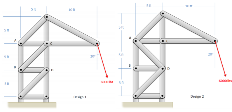
    You are asked to compare two crane truss designs as shown below. Find the forces in members AB, BC, and CD for Design 1 and find forces AB, AD, and CD for Design 2. What member is subjected to the highest loads in either case?

    Two versions of a 13-member crane truss design: both include two square subunits with 5-foot sides, stacked on one top of the other, with the top subunit for each design having the corners A top left, B bottom left, C top right, and D bottom right. At the tower top, a 5-ft vertical beam extends above C and is connected by another beam to A; a 10-ft horizontal beam extends to the right of C and is connected to the top end of the vertical beam as well. Both designs are connected to the ground with pin supports and have 6000-lb forces applied at the right end of the 10-ft beam, pointing down and to the right at 20° from the vertical. The difference is in the orientation of the diagonal support beams in the square subunits: in design 1 the supports are member BC in the upper unit and the parallel member in the lower unit; in design 2 the supports are member AD in the upper unit and a member that would be parallel to BC in the lower unit.
    Figure \(\PageIndex{6}\): problem diagram for Exercise \(\PageIndex{6}\). Two versions of a crane truss design that differ only in the orientation of their support beams.
    Solution

    Design 1: \(F_{AB} = 11,276\) lbs T, \(F_{BC} = 2902\) lbs T, \(F_{CD} = 18,967\) lbs C

    Design 2: \(F_{AB} = 13,322\) lbs T, \(F_{AD} = 2902\) lbs C, \(F_{CD} = 16,914\) lbs C

    The largest forces are in member CD for both designs.

    Exercise \(\PageIndex{7}\)

    The K truss shown below supports three loads. Assume only vertical reaction forces at the supports. Use the method of sections to determine the forces in members AB and FG. (Hint: you will need to cut through more than three members, but you can use your moment equations strategically to solve for exactly what you need).
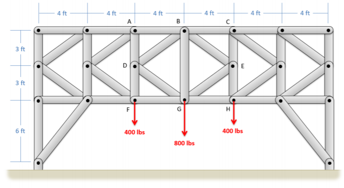
    A truss consisting of 6 subunits in a horizontal row: the center left subunit consists of horizontal 4-ft member AB, a 3-ft vertical member AD extending down from A, another 3-ft vertical member DF extending down from D, a horizontal 4-ft member FG, and two diagonal members BD and DG. The center of the whole truss is vertical member BG. The center right subunit consists of horizontal 4-ft member BC, a 3-ft vertical member CE extending down from C, a 3-ft vertical member EH extending down from E, a horizontal 4-ft member GH, and two diagonal members BE and EG. 2 subunits identical to the center left subunit are attached to the left of the center right subunit, and 2 copies of the right subunit are attached to the right side of the center right subunit. The outermost subunit on either side is supported by a 6-ft vertical beam extending below the outer edge, with that beam's lower end connecting to the subunit's inner edge by another beam. Both points of attachment to the ground are pin supports. A downwards force of 400 lbs is applied at points F and H, and another downwards force of 800 lbs is applied at G.
    Figure \(\PageIndex{7}\): problem diagram for Exercise \(\PageIndex{7}\). A two-dimensional representation of a K-truss which experiences downwards forces applied at three points.
    Solution

    \(F_{AB} = 1066.67\) lbs C, \(F_{FG} = 1066.67\) lbs T

    Exercise \(\PageIndex{8}\)

    The truss shown below is supported by a pin support at A and a roller support at B. Use the hybrid method of sections and joints to determine the forces in members CE, CF, and CD.
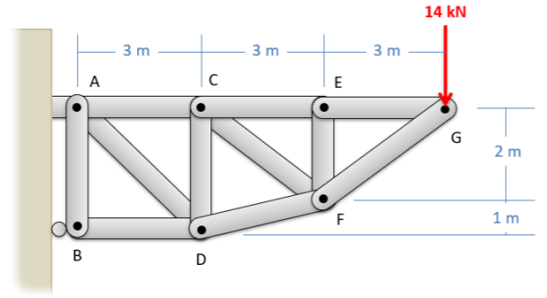
    A truss attached to a wall at its leftmost end: a square subunit of members 3 meters long, with corners labeled A, C, D, B clockwise from the upper left, is attached to the wall as described above. A 3-meter horizontal member CE extends rightwards from C, and a diagonal member DF extends 1 meter upwards from D, ending directly below point E. A vertical beam connects E and F; diagonal supports connect points A and D, and points C and F. A 3-meter horizontal member EG extends rightwards from E, and a diagonal member connects F and G. A downwards 14 kN force is applied at point G.
    Figure \(\PageIndex{8}\): problem diagram for Exercise \(\PageIndex{9}\). A two-dimensional representation of a truss attached to a wall, experiencing a downwards force at one point.
    Solution

    \(F_{CE} = 21\) kN T, \(F_{CF} = 8.41\) kN T, \(F_{CD} = 4.67\) kN C

    Exercise \(\PageIndex{9}\)

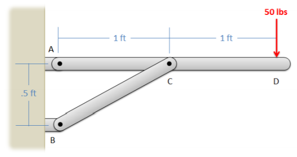
    The shelf shown below is used to support a 50-lb weight. Determine the forces on members ACD and BC in the structure. Draw those forces on diagrams of each member.

    Side view of a wall-mounted horizontal shelf, consisting of a horizontal 2-foot member ACD where the left endpoint A is attached to the wall by a pin support and a diagonal support member BC. Point B, located 0.5 feet below A, is attached to the wall by a pin support and point C is the midpoint of AD. A downwards force of 50 lbs is applied at point D.
    Figure \(\PageIndex{9}\): problem diagram for Example \(\PageIndex{9}\). Side view of a wall-mounted horizontal shelf supporting a weight at its free end.
    Solution

    \(F_{BC} = 223.6\) lbs (Compression), \(F_{A_X} = -200\) lbs, \(F_{A_Y} = -50\) lbs

    Exercise \(\PageIndex{10}\)

    A 20 N force is applied to a can-crushing mechanism as shown below. If the distance between points C and D is 0.1 meters, what are the forces being applied to the can at points B and D? (Hint: treat the can as a two-force member)

    Side view of a wall-mounted can-crushing mechanism: a 0.4-meter diagonal member ABC, making a 25° angle with the horizontal, has its lower right endpoint C attached to the wall with a pin support. Point B, which is 0.1 meter from C, is the point of attachment for a short member that crosses ABC so as to make an X shape. Point D, which is 0.1 meter below C and also attached to the wall with a pin support, is the point of attachment for another short member parallel to the one at B. The two short members hold a soda can between them, being in contact with its top and bottom. A 20-Newton force, downwards and to the left, is applied at point A, perpendicular to member ABC.
    Figure \(\PageIndex{10}\): problem diagram for Exercise \(\PageIndex{10}\). Side view of a wall-mounted can-crushing mechanism that holds a soda can and experiences an applied force at its handle end.
    Solution

    \(F_{can} = 148.9\) N (Compression)

    Exercise \(\PageIndex{11}\)

    The suspension system on a car is shown below. Assuming the wheel is supporting a load of 3300 N and assuming the system is in equilibrium, what is the force we would expect in the shock absorber (member AE)? You can assume all connections are pin joints.
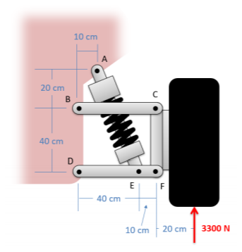
    Side view of a car's suspension system: two horizontal 50-cm members BC and DEF are attached to the main car body at their left endpoints, point B being 40 cm above point D. A vertical member connects the right endpoints C and F. A diagonal member connects point E, which is 10 cm left of F, and point A, which is 20 cm above and 10 cm to the right of point B. The car wheel, attached to the right side of CF, experiences an upwards 3300 N force applied at its bottom, 20 cm to the right of point F.
    Figure \(\PageIndex{11}\): problem diagram for Exercise \(\PageIndex{11}\). Side view of the suspension system of one wheel of a car, experiencing an upwards force on the wheel.
    Solution

    \(F_{AE} = 4611.9\) N (Compression)

    Exercise \(\PageIndex{12}\)

    The chair shown below is subjected to forces at A and B by a person sitting in the chair. Assuming that normal forces exist at F and G, and that friction forces only act at point G (not at F), determine all the forces acting on each of the three members in the chair. Draw these forces acting on each part of the chair on a diagram.
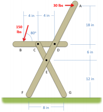
    Side view of a square-seat, left-facing folding chair. Seat is 18 inches above the ground and consists of a horizontal member BCD, with BC and CD each 4 inches long. Diagonal member CEG slants down and to the right from point C, with E 12 inches above the ground and G in contact with the ground. A second diagonal member ADEF slants up and to the right from F, its point of contact with the ground, and ends with point A at 18 inches above the seat. Points F and G are 8 inches apart. A rightwards force of 30 lb is applied at point A, and a diagonal force of 150 lbs, pointing down and to the left with the vector arrow at 80° above the horizontal, is applied at point B.
    Figure \(\PageIndex{12}\): problem diagram for Exercise \(\PageIndex{12}\). Side view of a folding chair with a square seat, facing to the left, that experiences forces at two points from a person sitting in the chair.
    Solution

    \(F_F = 108.3\) lbs, \(F_{G_X} = -3.95\) lbs, \(F_{G_Y} = 39.5\) lbs

    \(F_{C_X} = \pm \, 16.89\) lbs, \(F_{C_Y} = \pm \, 295.4\) lbs

    \(F_{D_X} = \pm \, 142.9\) lbs, \(F_{D_Y} = \pm \, 147.7\) lbs

    \(F_{E_X} = \pm \, 112.9\) lbs, \(F_{E_Y} = \pm \, 256.0\) lbs


    This page titled 5.8: Chapter 5 Homework Problems is shared under a CC BY-SA 4.0 license and was authored, remixed, and/or curated by Jacob Moore & Contributors (Mechanics Map) via source content that was edited to the style and standards of the LibreTexts platform; a detailed edit history is available upon request.