Engineering LibreTexts

6.3: Wedges

  • Page ID
    53829
  • \( \newcommand{\vecs}[1]{\overset { \scriptstyle \rightharpoonup} {\mathbf{#1}} } \) \( \newcommand{\vecd}[1]{\overset{-\!-\!\rightharpoonup}{\vphantom{a}\smash {#1}}} \)\(\newcommand{\id}{\mathrm{id}}\) \( \newcommand{\Span}{\mathrm{span}}\) \( \newcommand{\kernel}{\mathrm{null}\,}\) \( \newcommand{\range}{\mathrm{range}\,}\) \( \newcommand{\RealPart}{\mathrm{Re}}\) \( \newcommand{\ImaginaryPart}{\mathrm{Im}}\) \( \newcommand{\Argument}{\mathrm{Arg}}\) \( \newcommand{\norm}[1]{\| #1 \|}\) \( \newcommand{\inner}[2]{\langle #1, #2 \rangle}\) \( \newcommand{\Span}{\mathrm{span}}\) \(\newcommand{\id}{\mathrm{id}}\) \( \newcommand{\Span}{\mathrm{span}}\) \( \newcommand{\kernel}{\mathrm{null}\,}\) \( \newcommand{\range}{\mathrm{range}\,}\) \( \newcommand{\RealPart}{\mathrm{Re}}\) \( \newcommand{\ImaginaryPart}{\mathrm{Im}}\) \( \newcommand{\Argument}{\mathrm{Arg}}\) \( \newcommand{\norm}[1]{\| #1 \|}\) \( \newcommand{\inner}[2]{\langle #1, #2 \rangle}\) \( \newcommand{\Span}{\mathrm{span}}\)\(\newcommand{\AA}{\unicode[.8,0]{x212B}}\)

    A wedge is a thin, inclined-plane-shaped object that is used to force two objects apart or to force one object away from a nearby surface. Wedges have the effect of allowing users to create very large normal forces to move objects with relatively small input forces. The friction forces in wedge systems also tend to be very large, though, and can reduce the effectiveness of wedges.

    Free body diagram of an iron wedge pushed point-down into a log, splitting the wood. Contains the following labeled forces: a downwards pushing force on the base of the wedge, an upwards friction force on each of the two sides of the wedge in contact with the wood, and a normal force on each face of the wedge in contact with the wood, perpendicular to and pointing away from the point of contact.
    Figure \(\PageIndex{1}\): A hammer is used to push this wedge into the crack in this log. The normal forces are pushing the two halves of the log apart while the friction forces are opposing the pushing force. Adapted from image by Luigi Chiesa. CC-BY-SA-3.0.

    To analyze a wedge system, we will need to draw free body diagrams of each of the bodies in the system (the wedge itself and any bodies the wedge will be moving). We need to be sure that we include the pushing force on the wedge, normal forces along any surfaces in contact, and friction forces along any surfaces in contact.

    Side view of a wedge being used to pry a large safe away from a wall. Free body diagram of the wedge shows a downwards pushing force at its base, the two friction forces that point upwards and along the two sides of the wedge in contact with the wall and the safe, and the two normal forces perpendicular to those sides that are exerted on the wedge by the wall and the safe. Free body diagram of the safe shows the forces of its weight, its friction opposing the motion away from the wall, the normal force exerted on it by the floor, the normal force exerted on it by the wedge, and the the friction exerted on it by the wedge.
    Figure \(\PageIndex{2}\): The top diagram shows a wedge being used to push a safe away from a wall. The first step in analyzing the system is to draw free body diagrams of the wedge and the safe. Remember that all normal forces will be perpendicular to the surfaces in contact and that all friction forces will be parallel to the surfaces in contact.

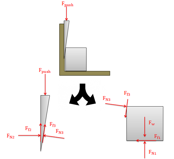
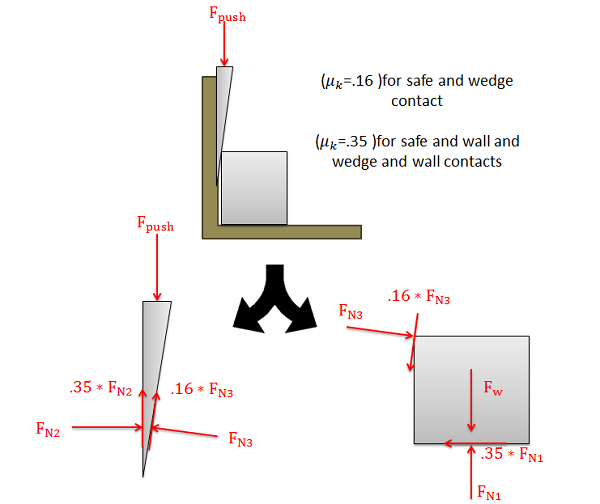
    After we draw the free body diagram, we can work to simplify the problem. It is usually assumed that the wedge and the bodies will be sliding against one another, so each friction force will be equal to the kinetic coefficient of friction between the two surfaces times the associated normal force between the two forces. This reduces the number of unknowns and will usually allow us to solve for any unknown values.

    The same problem diagram and free body diagrams from Figure 2 above, with the added information that the coefficient of kinetic friction between the safe and wedge is 0.16 and the coefficient of kinetic friction between the safe and wall, or between the safe and floor, is 0.35. The friction forces on the free body diagrams have been rewritten as the product of the appropriate normal forces and kinetic friction coefficient values.
    Figure \(\PageIndex{3}\): By replacing each of the friction forces with the kinetic coefficient of friction times the normal force, we can reduce the number of unknowns in our analysis.

    With our simplified diagram, we will assume that the bodies are all in equilibrium and write out equilibrium equations for the two bodies. By solving the equilibrium equations, we can solve for any unknowns we have.

    Video lecture covering this section, delivered by Dr. Jacob Moore. YouTube source: https://youtu.be/5R3S5bYBULY.

    Example \(\PageIndex{1}\)

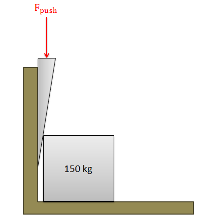
    A heavy safe is being pushed away from a wall with a wedge as shown below. Assume the wedge has an angle of 5 degrees, the coefficient of friction (static and kinetic) between the wedge and the safe is 0.16, and the coefficients of friction (static and kinetic) between the wedge and the wall and the safe and the floor are both 0.35. What is the pushing force required to move the safe out from the wall?

    A 150-kg safe is placed with its left side against a wall. A wedge is inserted point-down into the space between the wall and the safe's side, with a downwards pushing force applied at its base.
    Figure \(\PageIndex{4}\): problem diagram for Example \(\PageIndex{1}\). A point-down wedge, with a pushing force applied at its base, is used to pry a safe away from a wall.
    Solution
    Video \(\PageIndex{2}\): Worked solution to example problem \(\PageIndex{1}\), provided by Dr. Jacob Moore. YouTube source: https://youtu.be/r7Ut0GI8q00.

    Example \(\PageIndex{2}\)

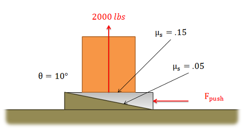
    A wedge as shown below is being used to lift the corner of the foundation of a house. How large must the pushing force be to exert a lifting force of one ton (2000 lbs)?

    A block sits on a 10-degree incline that slopes down from left to right, and a wedge is inserted between the block and incline, its point facing left, through a pushing force applied at its base. Coefficients of friction are given as 0.15 between the block and the wedge, and 0.05 between the inclined plane and the wedge.
    Figure \(\PageIndex{5}\): problem diagram for Example \(\PageIndex{2}\). A wedge is used to lift a block on a 10° incline with a force of 2000 lbs; coefficients of friction are given as 0.15 between the block and wedge, and 0.05 between the incline and the wedge.
    Solution
    Video \(\PageIndex{3}\): Worked solution to example problem \(\PageIndex{2}\), provided by Dr. Jacob Moore. YouTube source: https://youtu.be/kgfh4Mna63M.

    This page titled 6.3: Wedges is shared under a CC BY-SA 4.0 license and was authored, remixed, and/or curated by Jacob Moore & Contributors (Mechanics Map) via source content that was edited to the style and standards of the LibreTexts platform; a detailed edit history is available upon request.

    • Was this article helpful?