
6.6: Disc Friction
- Page ID
- 53832

Disc friction is the friction that exists between a stationary surface and the end of a rotating shaft, or other rotating body. Disc friction will tend to exert a moment on the bodies involved, resisting the relative rotation of the bodies. Disc friction is applicable to a wide variety of designs including end bearings, collar bearings, disc brakes, and clutches.
Hollow Circular Contact Area
To start our analysis of disc friction we will use the example of a collar bearing. In this type of bearing, we have a rotating shaft traveling through a hole in a surface. The shaft is supporting some load force as shown, and a collar is used to support the shaft itself. In this case we will have a hollow circular contact area between the rotating collar and the stationary surface.
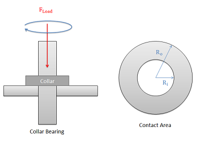
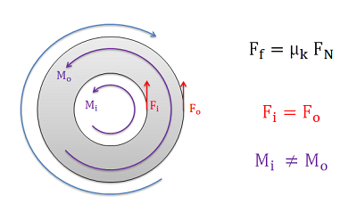
The friction force at any point in the contact area will be equal to the normal force at that point times the kinetic coefficient of friction at that point. If we assume a uniform pressure between the collar and the surface and a uniform coefficient of friction, then we will have the same friction force exerted at all points. However, this does not translate into an equal moment exerted by each point. Points further from the center of rotation will exert a larger moment than points closer to the center of rotation because they will have a larger moment arm.
\[ F_f = \mu_k \ F_N \] \[ F_i = F_o \] \[ M_i \neq M_o \]
To determine the net moment exerted by the friction forces, we will need to use calculus to sum up the individual moments over the entire contact area. The moment at each individual point will be equal to the kinetic coefficient of friction, times the normal force pressure at that point \((p)\), times the distance from that point to the center of rotation \((r)\).
\[ M = \int\limits_{A} dM = \int\limits_{A} (\mu_k) (p)(r) \, dA \]
To simplify things, we can move the constant coefficient of friction and the constant normal force pressure term outside the integral. We can also replace the pressure term with the load force on the bearing over the contact area. Finally, so that we can integrate over the range of \(R\) values, we can recognize that the rate of change in the area \((dA)\) for the hollow circular areas is simply the rate of change of the \(r\) term \((dr)\) times the circumference of the circle at \(r\). These changes lead to the equation below.
\[ M = \mu_k \left( \frac{F_{load}}{\pi (R_o^2 - R_i^2)} \right) \int\limits_{R_i}^{R_o} r (2 \pi r) \, dr \]
Finally, we can evaluate the integral from the inner radius to the outer radius. If we evaluate the integral and simplify, we will end up with the final equation below.
\[ M = \frac{2}{3} \mu_k \ F_{load} \left( \frac{R_o^3 - R_i^3}{R_o^2 - R_i^2} \right) \]
Solid Circular Contact Area
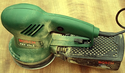
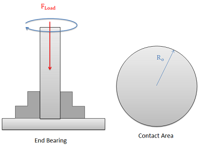
In cases where we have a solid circular contact area, such as a solid circular shaft in an end bearing or the orbital sander shown at the top of the page, we simply set the inner radius to zero and we can simplify the formula. If we do so, the original formula is reduced to the equation below.
\[ M = \frac{2}{3} \mu_k \ F_{load} \ R_o \]
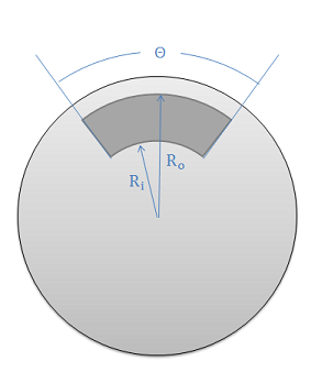
Circular Arcs (Disc Brakes)
In some cases, such as in disc brakes, we may have a contact area that looks like a section of the hollow circular contact area we had earlier. For this scenario we have less area on which the friction force can be exerted to cause a moment, but the smaller area also causes higher pressures in that contact area for the same load force. The end result is that these terms cancel each other out and we end up with the same formula we had for the hollow circular contact area when examining a single brake pad. Most disc brakes, however, have a pair of pads, one on each side of the rotating disc, so we will need to double the moment in our equation for the usual pair of pads.
\begin{align} \text{Single Brake Pad:} &\quad M = \frac{2}{3} \mu_k \ F_{load} \left( \frac{R_o^3 - R_i^3}{R_o^2 - R_i^2} \right) \\[6pt] \text{Brake Pad on Each Side:} &\quad M = \frac{4}{3} \mu_k \ F_{load} \left( \frac{R_o^3 - R_i^3}{R_o^2 - R_i^2} \right) \end{align}
The calculations above show that the contact angle \(theta\) is irrelevant to the stopping power of the brakes in theory. In practice, however, larger brake pads can slightly increase the stopping power of the brakes and provide other benefits such as better heat dissipation.
Example \(\PageIndex{1}\)
A disc sander is pressed against a wooden surface with a force of 50 N. Assuming the kinetic coefficient between the sanding pad and the wood is 0.6 and the diameter of the sanding disc is 0.2 meters, what is the torque the motor must exert to keep the disc spinning at a constant rate?
- Solution
-
Video \(\PageIndex{2}\): Worked solution to example problem \(\PageIndex{1}\), provided by Dr. Jacob Moore. YouTube source: https://youtu.be/0cBfIfDYDic.
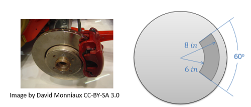
Example \(\PageIndex{2}\)
In the disc brake setup shown below, a pair of brake pads is pressed into the rotor with a force of 300 lbs. If the kinetic coefficient of friction between the brake pads and the rotor is 0.4, find the stopping torque exerted by the brake pads.
- Solution
-
Video \(\PageIndex{3}\): Worked solution to example problem \(\PageIndex{2}\), provided by Dr. Jacob Moore. YouTube source: https://youtu.be/lYrN0zr6kF8.