Engineering LibreTexts

12.3: Rigid-Body General Planar Motion

  • Page ID
    54795
  • \( \newcommand{\vecs}[1]{\overset { \scriptstyle \rightharpoonup} {\mathbf{#1}} } \) \( \newcommand{\vecd}[1]{\overset{-\!-\!\rightharpoonup}{\vphantom{a}\smash {#1}}} \)\(\newcommand{\id}{\mathrm{id}}\) \( \newcommand{\Span}{\mathrm{span}}\) \( \newcommand{\kernel}{\mathrm{null}\,}\) \( \newcommand{\range}{\mathrm{range}\,}\) \( \newcommand{\RealPart}{\mathrm{Re}}\) \( \newcommand{\ImaginaryPart}{\mathrm{Im}}\) \( \newcommand{\Argument}{\mathrm{Arg}}\) \( \newcommand{\norm}[1]{\| #1 \|}\) \( \newcommand{\inner}[2]{\langle #1, #2 \rangle}\) \( \newcommand{\Span}{\mathrm{span}}\) \(\newcommand{\id}{\mathrm{id}}\) \( \newcommand{\Span}{\mathrm{span}}\) \( \newcommand{\kernel}{\mathrm{null}\,}\) \( \newcommand{\range}{\mathrm{range}\,}\) \( \newcommand{\RealPart}{\mathrm{Re}}\) \( \newcommand{\ImaginaryPart}{\mathrm{Im}}\) \( \newcommand{\Argument}{\mathrm{Arg}}\) \( \newcommand{\norm}[1]{\| #1 \|}\) \( \newcommand{\inner}[2]{\langle #1, #2 \rangle}\) \( \newcommand{\Span}{\mathrm{span}}\)\(\newcommand{\AA}{\unicode[.8,0]{x212B}}\)

    In general planar motion, bodies are both rotating and translating at the same time. As a result, we will need to relate the forces to the acceleration of the center of mass of the body as well as relating the moments to the angular accelerations.

    A boy running along a beach, rolling a tire on its side.
    Figure \(\PageIndex{1}\): This tire being rolled along the ground is an example of general planar motion. The tire is both translating and rotating as it is pushed along. Image by Joy Agyepong, CC-BY-SA 4.0.

    To analyze a body undergoing general planar motion, we will start by drawing a free body diagram of the body in motion. Be sure to identify the center of mass, as well as identifying all known and unknown forces, and known and unknown moments acting on the body. It is also sometimes helpful to label any key dimensions as well as using dashed lines to identify any known accelerations or angular accelerations.

    Next, we move on to identifying the equations of motion. At its core, this means going back to Newton's Second Law. Since this is a rigid body system, we include both the translational and rotational versions.

    \[ \sum \vec{F} = m * \vec{a} \]

    \[ \sum \vec{M} = I * \vec{\alpha} \]

    As we did with the previous translational systems, we will break the force equation into components, turning the one vector equation into two scalar equations. Additionally, it's important to always use the center of mass for the accelerations in our force equations and take the moments and moment of inertia about the center of mass for our moment equation.

    \[ \sum F_x = m * a_x \]

    \[ \sum F_y = m * a_y \]

    \[ \sum M_{COM} = I * \alpha \]

    Plugging the known forces, moments, and accelerations into the above equations, we can solve for up to three unknowns. If more than three unknowns exist in the equations, we will sometimes have to go back to kinematics to relate quantities such as acceleration and angular acceleration.

    Video lecture covering this section, delivered by Dr. Jacob Moore. YouTube source: https://youtu.be/jhVDM7Zw_LM.

    Example \(\PageIndex{1}\)

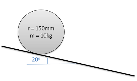
    A cylinder with a radius of 0.15 m and a mass of 10 kg is placed on a ramp at a 20-degree angle. If the cylinder is released from rest and rolls without slipping, what is the initial angular acceleration of the cylinder and the time required for the cylinder to roll 5 meters?

    Side view of a cylinder of radius 150 millimeters and mass 10 kilograms. The cylinder is located at the top of a ramp that makes a 20° angle with the ground.
    Figure \(\PageIndex{2}\): problem diagram for Example \(\PageIndex{1}\). A uniform cylinder rolls down a ramp that has a 20° incline.
    Solution
    Video \(\PageIndex{2}\): Worked solution to example problem \(\PageIndex{1}\), provided by Dr. Majid Chatsaz. YouTube source: https://youtu.be/oQFVVC3SzZ0.

    Example \(\PageIndex{2}\)

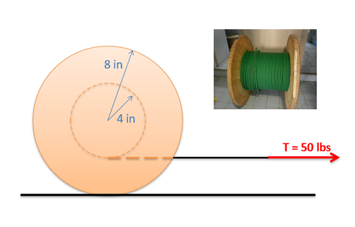
    The cable spool shown below has a weight of 50 lbs and has a moment of inertia of 0.28 slug-ft2. Assume the spool rolls without slipping when we apply a 50-lb tension in the cable.

    • What is the friction force between the spool and the ground?
    • What is the acceleration of the center of mass of the spool?
    A small photograph shows a cable spool consisting of a wooden cylinder around which the cable is wound, sandwiched at its two bases by two larger-diameter wooden disks. A diagram shows a side view of this spool, with only one of the outer disks visible: the inner cylinder has a radius of 4 inches and the outer disks have radius 8 inches. The spool is lying on a flat surface, and the free end of the cable around its inner cylinder is being pulled to the right by a tension force of 50 lbs. The portion of the cable being pulled extends horizontally from the lowest point on the inner cylinder.
    Figure \(\PageIndex{3}\): problem diagram for Example \(\PageIndex{2}\). A cable spool, consisting of a central cylinder the cable wraps around sandwiched between two larger disks at its bases, is pulled to the right by a tension force on the free end of the cable. Spool image by Seeweb, CC-BY-SA 2.0.
    Solution
    Video \(\PageIndex{3}\): Worked solution to example problem \(\PageIndex{2}\), provided by Dr. Majid Chatsaz. YouTube source: https://youtu.be/RAhLP-kMYaQ.

    Example \(\PageIndex{3}\)

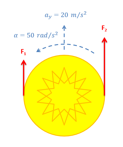
    You are designing a Frisbee launcher to launch a 40-cm-diameter, 0.6 kg Frisbee that can be modeled as flat circular disc. If you want the Frisbee to have a linear acceleration of 20 m/s2 and an angular acceleration of 50 rad/s2 as shown below, what should \(F_1\) and \(F_2\) be?

    A large yellow circle representing the Frisbee is accelerating linearly towards the top of the page, at a rate of 20 m/s². It is also rotating counterclockwise, with an angular acceleration of 50 rad/s² in the same direction. The circle experiences Force 1 applied at its leftmost point and Force 2 applied at its rightmost point, with both force vectors pointing vertically towards the top of the page.
    Figure \(\PageIndex{4}\): problem diagram for Example \(\PageIndex{3}\). A Frisbee, represented as a circle, accelerates both linearly and angularly as a result of experiencing two forces applied in the same direction at locations on opposite sides of a diameter.
    Solution
    Video \(\PageIndex{4}\): Worked solution to example problem \(\PageIndex{3}\), provided by Dr. Majid Chatsaz. YouTube source: https://youtu.be/DY9B7oU0j7k.

    Example \(\PageIndex{4}\)

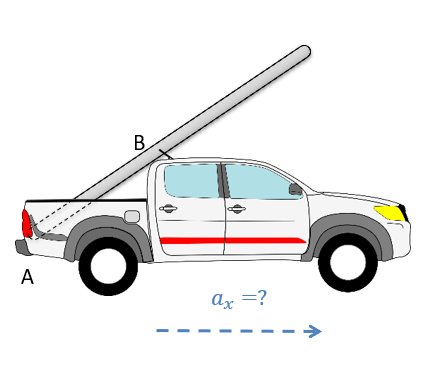
    A pickup truck is carrying a 30-kg, 6-meter-long ladder at a 35-degree angle as shown below. The ladder is wedged against the tailgate at A and makes contact with the roof of the truck at B. The distance from A to B is 2 meters. At what rate of acceleration would we expect the ladder to start to rotate upwards?

    A pickup truck is facing towards the right and accelerating in that direction. A ladder being carried by the truck makes contact with the truck bed and tailgate at point A, then slants upward and to the right to make contact with the top of the truck cab at point B along the way.
    Figure \(\PageIndex{5}\): problem diagram for Example \(\PageIndex{4}\). A moving pickup truck carries a ladder that leans forward, with its lower end propped against the tailgate.
    Solution
    Video \(\PageIndex{5}\): Worked solution to example problem \(\PageIndex{4}\), provided by Dr. Majid Chatsaz. YouTube source: https://youtu.be/UO5XsDFxQoY.

    This page titled 12.3: Rigid-Body General Planar Motion is shared under a CC BY-SA 4.0 license and was authored, remixed, and/or curated by Jacob Moore & Contributors (Mechanics Map) via source content that was edited to the style and standards of the LibreTexts platform; a detailed edit history is available upon request.