
17.5: Area Moments of Inertia via Integration
- Page ID
- 55342

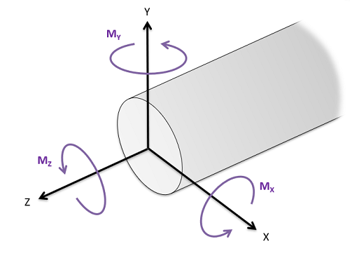
Area moments of inertia are used in engineering mechanics courses to determine a body's resistance to bending loads or torsional loads. Specifically, the area moment of inertia refers to the second area moment integral of a shape, with \(I_{xx}\) representing the moment of inertia about the \(x\)-axis, \(I_{yy}\) representing the moment of inertia about the \(y\)-axis, and \(J_{zz}\) (also called the polar moment of inertia) representing the moment of inertia about the \(z\)-axis. The moment of inertia about each axis represents the shapes resistance to a moment applied about that respective axis. Moments about the \(x\)- and \(y\)-axes would tend to bend an object, while moments about the \(z\)-axis would tend to twist the body.
Just as with centroids, each of these moments of inertia can be calculated via integration or by using the method of composite parts and the parallel axis theorem. On this page we are going to focus on calculating the area moments of inertia via moment integrals.
Bending Stresses and the Second Area Moment
When an object is subjected to a bending moment, that body will experience both internal tensile stresses and compressive stresses as shown in the diagram below. These stresses exert a net moment to counteract the loading moment, but exert no net force so that the body remains in equilibrium.
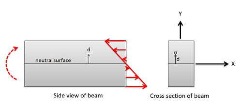
As we can see in the diagram, there is some central plane along which there are no tensile or compressive stresses. This is known as the neutral surface, and if there are no other forces present it will run through the centroid of the cross section. As we move up or down from the neutral surface, the stresses increase linearly. The moment exerted by this stress at any point will be the stress times the moment arm, which also linearly increases as we move away from the neutral surface. This means that the resistance to bending provided by any point in the cross section is directly proportional to the distance from the neutral axis squared. We can sum up the resistances to bending then by using the second rectangular area moment of inertia, where our distances are measured from the neutral axis.
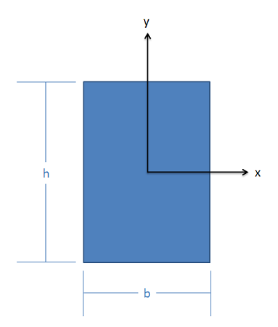
\[ I = \int_A (dA * d^2) \] Assuming we put the origin point at the centroid and that the \(x\)-axis is the neutral surface, the distance from the neutral surface to any point is simply the \(y\) coordinate of that point. Similarly, if we apply a moment about the \(y\)-axis, and had a neutral surface that ran along the \(y\)-axis, the distance from the neutral axis would simply be the \(x\) coordinate of the point. For this reason, \(I_{xx}\) includes \(y\) as the distance, while \(I_{yy}\) includes \(x\) as the distance.
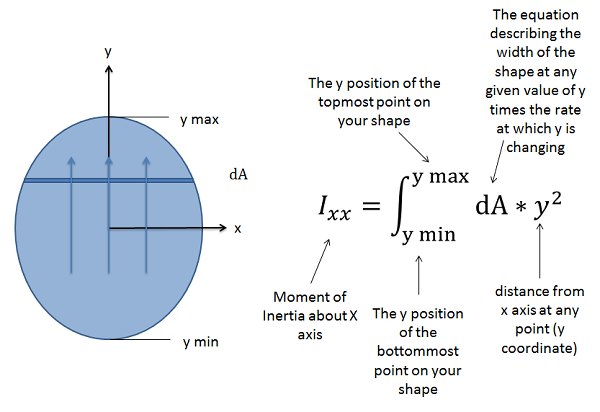
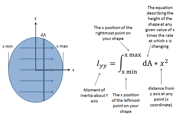
\[ I_{xx} = \int_{y_{min}}^{y_{max}} (dA * y^2) \quad\quad\quad I_{yy} = \int_{x_{min}}^{x_{max}} (dA * x^2) \]
Calculating the Rectangular Area Moment of Inertia via Integration
To determine the area moment of inertia, start by drawing out the area under analysis, and include the axes you are taking the moment of inertia about. This is important, since the moment of inertia will vary depending on the axis chosen. In cases on bending stresses you will want to put the origin on the neutral surface, which will be at the centroid of the area. If the centroid is not given to you, you will need to determine the centroid as discussed in prior sections.
To take the moment of inertia about the \(x\)-axis through this point (\(I_{xx}\)) we will use the general formula discussed earlier. We will be moving from bottom to top, integrating the rate of change of the area as we go, and multiplying that by the \(y\)-value squared. The rate of change of area (\(dA\)) as we move upwards will be the width of the object at any given \(y\)-value times the rate at which we are moving. Unless the width remains constant, the width will need to be represented as a mathematical function in terms of \(y\).
To find the moment of inertia about the \(y\)-axis through a given point (\(I_{yy}\)) we will move left to right, using the distances from the \(y\)-axis in our moment integral (in this case the \(x\) coordinates of each point). Moving from left to right, the rate of change of the area will be the height of the shape at any given \(x\)-value times the rate at which we are moving left to right. Again, we will need to describe this with an mathematical function if the height is not constant. We will multiply this function by the \(x\)-value squared for the second moment integral, and this will give us the moment of inertia about the \(y\)-axis.
Torsional Stresses and the Polar Moment of Inertia
When an object is subjected to a torsional moment, that object will experience internal shearing forces as shown in the diagram below. These stresses are oriented in such a way that they will counteract the torsional moment, but do not exert any net force on the shaft so that shaft stays in equilibrium.
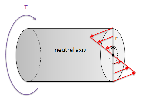
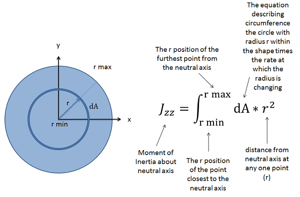
As we can see in the diagram, there is a central axis along which there are no shearing stresses. This is known as the neutral axis, and if there are no other forces present, then this will travel through the centroid of the shaft's cross section. As we move away from the neutral axis in any direction, the stresses will increase linearly. The moment exerted by the stress at any point will be the stress times the moment arm, which also increases linearly as we move away from the neutral axis. This means that the resistance to torsional loading provided by any one point on the cross section is directly proportional the square of the distance between the point and neutral axis. We can sum up the resistances to torsional loading then using the second polar area moment of inertia, where our distances are measured from the neutral axis (\(r\)), a single point in the shaft's cross-section.
\[ J_{zz} = \int_{r_{min}}^{r_{max}} (dA * r^2) \]
Calculating the Polar Area Moment of Inertia via Integration
The first step in determining the polar moment of inertia is to draw the area and identify the point about which we are taking the moment of inertia. In the case of torsional loading, we will usually want to pick the point at which the neutral axis travels through the shaft's cross section, which in the absence of other types of loading will be the centroid of the cross section. If the centroid is not clearly identified, you will need to determine the centroid as discussed in previous sections.
To take the moment of inertia about this central point, we will be measuring all distances outward from this point. Rather than moving left to right or top to bottom, we will instead be integrating from the center radiating outward in all directions. We will be going from the minimum distance from the center for our shape (zero unless there is a central hole in our area) to the maximum distance to the center. We will again be integrating the rate of change of area, which in this case will be a function for the circumference at a given radius times the rate as which we are moving outwards times the given radius squared.
Example \(\PageIndex{1}\)
Find the rectangular moments of inertia for this shape about both the \(x\)-axis and \(y\)-axis though the centroid. Leave the answer in terms of the generic width (\(b\)) and height (\(h\)) of the rectangle.
- Solution:
-
Video \(\PageIndex{2}\): Worked solution to example problem \(\PageIndex{1}\), provided by Dr. Jacob Moore. YouTube source: https://youtu.be/PL6QIBL_rPw.
Example \(\PageIndex{2}\)
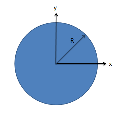
Find the polar moments of inertia for this circular area about its centroid. Leave the answer in terms of the generic radius \(R\).
- Solution:
-
Video \(\PageIndex{3}\): Worked solution to example problem \(\PageIndex{2}\), provided by Dr. Jacob Moore. YouTube source: https://youtu.be/peqSVmDjThA.
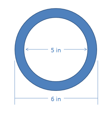
Exercise \(\PageIndex{3}\)
Find the polar moment of inertia of this hollow circular shape about its centroid.
- Solution:
-
Video \(\PageIndex{4}\): Worked solution to example problem \(\PageIndex{3}\), provided by Dr. Jacob Moore. YouTube source: https://youtu.be/Jw696gGSDM8.