
2.2: Pressure Vessels
- Page ID
- 44532

Introduction
A good deal of the Mechanics of Materials can be introduced entirely within the confines of uniaxially stressed structural elements, and this was the goal of the previous modules. But of course the real world is three-dimensional, and we need to extend these concepts accordingly. We now take the next step, and consider those structures in which the loading is still simple, but where the stresses and strains now require a second dimension for their description. Both for their value in demonstrating two-dimensional effects and also for their practical use in mechanical design, we turn to a slightly more complicated structural type: the thin-walled pressure vessel.
Structures such as pipes or bottles capable of holding internal pressure have been very important in the history of science and technology. Although the ancient Romans had developed municipal engineering to a high order in many ways, the very need for their impressive system of large aqueducts for carrying water was due to their not yet having pipes that could maintain internal pressure. Water can flow uphill when driven by the hydraulic pressure of the reservoir at a higher elevation, but without a pressure-containing pipe an aqueduct must be constructed so the water can run downhill all the way from the reservoir to the destination.
Airplane cabins are another familiar example of pressure-containing structures. They illustrate very dramatically the importance of proper design, since the atmosphere in the cabin has enough energy associated with its relative pressurization compared to the thin air outside that catastrophic crack growth is a real possibility. A number of fatal commercial tragedies have resulted from this, particularly famous ones being the Comet aircraft that disintegrated in flight in the 1950’s(1T. Bishop, “Fatigue and the Comet Disasters,” Metal Progress, Vol. 67, pp. 79–85, May 1955.) and the loss of a 5-meter section of the roof in the first-class section of an Aloha Airlines B737 in April 1988(E.E. Murphy, “Aging Aircraft: Too Old to Fly?” IEEE Spectrum, pp. 28–31, June 1989.)
In the sections to follow, we will outline the means of determining stresses and deformations in structures such as these, since this is a vital first step in designing against failure.
Stresses
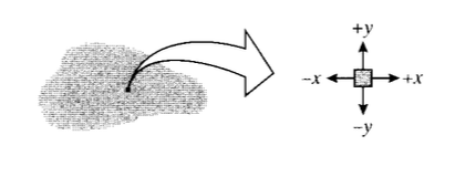
In two dimensions, the state of stress at a point is conveniently illustrated by drawing four perpendicular lines that we can view as representing four adjacent planes of atoms taken from an arbitrary position within the material. The planes on this “stress square” shown in Figure 1 can be identified by the orientations of their normals; the upper horizontal plane is a \(+y\) plane, since its normal points in the \(+y\) direction. The vertical plane on the right is a \(+x\) plane. Similarly, the left vertical and lower horizontal planes are \(-y\) and \(-x\), respectively.
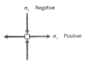
The sign convention in common use regards tensile stresses as positive and compressive stresses as negative. A positive tensile stress acting in the \(x\) direction is drawn on the \(+x\) face as an arrow pointed in the \(+x\) direction. But for the stress square to be in equilibrium, this arrow must be balanced by another acting on the \(-x\) face and pointed in the \(-x\) direction. Of course, these are not two separate stresses, but simply indicate the stress state is one of uniaxial tension. A positive stress is therefore indicated by a + arrow on a + face, or a - arrow on a - face. Compressive stresses are the reverse: a - arrow on a + face or a + arrow on a - face. A stress state with both positive and negative components is shown in Figure 2.
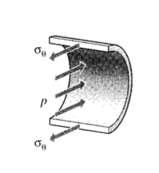
Consider now a simple spherical vessel of radius \(r\) and wall thickness \(b\), such as a round balloon. An internal pressure \(p\) induces equal biaxial tangential tensile stresses in the walls, which can be denoted using spherical \(r\theta \phi\) coordinates as \(\sigma_{\theta}\) and \(\sigma_{\phi}\).
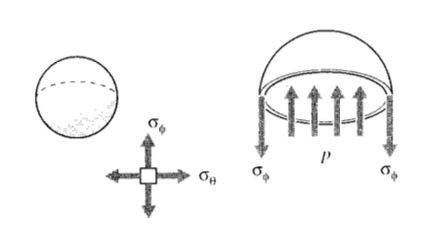
The magnitude of these stresses can be determined by considering a free body diagram of half the pressure vessel, including its pressurized internal fluid (see Figure 3). The fluid itself is assumed to have negligible weight. The internal pressure generates a force of \(pA = p(\pi r^2)\) acting on the fluid, which is balanced by the force obtained by multiplying the wall stress times its area, \(\sigma_{\phi} (2\pi rb)\). Equating these:
\[p(\pi r^2) = \sigma_{\phi} (2\pi rb)\nonumber\]
\[\sigma_{\phi} = \dfrac{pr}{2b}\]
Note that this is a statically determined result, with no dependence on the material properties. Further, note that the stresses in any two orthogonal circumferential directions are the same; i.e. \(\sigma_{\phi} = \sigma_{\theta}\).
The accuracy of this result depends on the vessel being “thin-walled,” i.e. \(r \gg b\). At the surfaces of the vessel wall, a radial stress \(\sigma_r\) must be present to balance the pressure there. But the inner-surface radial stress is equal to \(p\), while the circumferential stresses are \(p\) times the ratio (\(r/2b\)). When this ratio is large, the radial stresses can be neglected in comparison with the circumferential stresses.
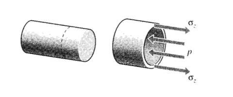
The stresses \(\sigma_z\) in the axial direction of a cylindrical pressure vessel with closed ends are found using this same approach as seen in Figure 4, and yielding the same answer:
\[p(\pi r^2) =\sigma_z (2\pi r) b\nonumber\]
\[\sigma_z = \dfrac{pr}{2b}\]
However, a different view is needed to obtain the circumferential or “hoop” stresses σθ. Considering an axial section of unit length, the force balance for Figure 5 gives
\[2 \sigma_{\theta} (b \cdot 1) = p(2r \cdot 1)\nonumber\]
\[\sigma_{\theta} =\dfrac{pr}{b}\]
Note the hoop stresses are twice the axial stresses. This result — different stresses in different directions — occurs more often than not in engineering structures, and shows one of the compelling advantages for engineered materials that can be made stronger in one direction than another (the property of anisotropy). If a pressure vessel constructed of conventional isotropic material is made thick enough to keep the hoop stresses below yield, it will be twice as strong as it needs to be in the axial direction. In applications placing a premium on weight this may well be something to avoid.
Example \(\PageIndex{1}\)
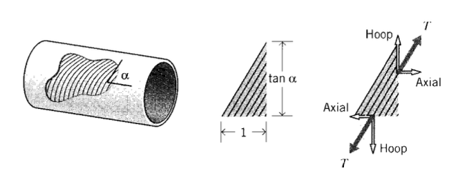
Consider a cylindrical pressure vessel to be constructed by filament winding, in which fibers are laid down at a prescribed helical angle \(\alpha\) (see Figure 6). Taking a free body of unit axial dimension along which \(n\) fibers transmitting tension \(T\) are present, the circumferential distance cut by these same \(n\) fibers is then \(\tan \alpha\). To balance the hoop and axial stresses, the fiber tensions must satisfy the relations
hoop: \(nT \sin \alpha = \dfrac{pr}{b} (1) (b)\)
axial: \(nT \cos \alpha = \dfrac{pr}{2b} (\tan \alpha) (b)\)
Dividing the first of these expressions by the second and rearranging, we have
\[\tan^2 \alpha = 2, \alpha = 54.7^{\circ}\nonumber\]
This is the “magic angle” for filament wound vessels, at which the fibers are inclined just enough toward the circumferential direction to make the vessel twice as strong circumferentially as it is axially. Firefighting hoses are also braided at this same angle, since otherwise the nozzle would jump forward or backward when the valve is opened and the fibers try to align themselves along the correct direction.
Deformation: the Poisson effect
When a pressure vessel has open ends, such as with a pipe connecting one chamber with another, there will be no axial stress since there are no end caps for the fluid to push against. Then only the hoop stress \(\sigma_{\theta} = pr/b\) exists, and the corresponding hoop strain is given by Hooke’s Law as:
\[\epsilon_{\theta} = \dfrac{\sigma_{\theta}}{E} = \dfrac{pr}{bE}\nonumber\]
Since this strain is the change in circumference \(\delta C\) divided by the original circumference \(C = 2\pi r\) we can write:
\[\delta_C = C_{\epsilon_{\theta}} = 2\pi r \dfrac{pr}{bE}\nonumber\]
The change in circumference and the corresponding change in radius \(\delta_r\) are related by \(delta_r = \delta_C /2\pi, so the radial expansion is:
\[\delta_r = \dfrac{pr^2}{bE}\]
This is analogous to the expression \(\delta = PL/AE\) for the elongation of a uniaxial tensile specimen.
Example \(\PageIndex{2}\)
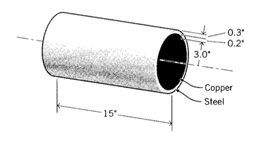
Consider a compound cylinder, one having a cylinder of brass fitted snugly inside another of steel as shown in Figure 7 and subjected to an internal pressure of \(p = 2\) Mpa.
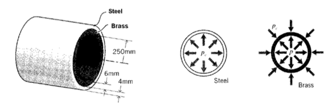
When the pressure is put inside the inner cylinder, it will naturally try to expand. But the outer cylinder pushes back so as to limit this expansion, and a “contact pressure” \(p_c\) develops at the interface between the two cylinders. The inner cylinder now expands according to the difference \(p - p_c\), while the outer cylinder expands as demanded by \(p_c\) alone. But since the two cylinders are obviously going to remain in contact, it should be clear that the radial expansions of the inner and outer cylinders must be the same, and we can write
\[\delta_b = \delta_s \to \dfrac{(p - p_c) r_b^2}{E_b b_b} = \dfrac{p_c r_s^2}{E_s b_s}\nonumber\]
where the \(a\) and \(s\) subscripts refer to the brass and steel cylinders respectively.
Substituting numerical values and solving for the unknown contact pressure \(p_c\):
\[p_c = 976 \text{ KPa}\nonumber\]
Now knowing \(p_c\), we can calculate the radial expansions and the stresses if desired. For instance, the hoop stress in the inner brass cylinder is
\[\sigma_{\theta, b} = \dfrac{(p - p_c) r_b}{b_b} = 62.5 \text{ MPa} (= 906 \text{ psi})\nonumber\]
Note that the stress is no longer independent of the material properties (\(E_b\) and \(E_s\)), depending as it does on the contact pressure pc which in turn depends on the material stiffnesses. This loss of statical determinacy occurs here because the problem has a mixture of some load boundary values (the internal pressure) and some displacement boundary values (the constraint that both cylinders have the same radial displacement.)
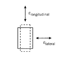
If a cylindrical vessel has closed ends, both axial and hoop stresses appear together, as given by Eqns. 2.2.2 and 2.2.3. Now the deformations are somewhat subtle, since a positive (tensile) strain in one direction will also contribute a negative (compressive) strain in the other direction, just as stretching a rubber band to make it longer in one direction makes it thinner in the other directions (see Figure 8). This lateral contraction accompanying a longitudinal extension is called the Poisson effect,(After the French mathematician Simeon Denis Poisson, (1781–1840).) and the Poisson’s ratio is a material property defined as
\[\nu = \dfrac{-\epsilon_{\text{lateral}}}{\epsilon_{\text{longitudinal}}}\]
where the minus sign accounts for the sign change between the lateral and longitudinal strains. The stress-strain, or “constitutive,” law of the material must be extended to include these effects, since the strain in any given direction is influenced by not only the stress in that direction, but also by the Poisson strains contributed by the stresses in the other two directions.
A material subjected only to a stress \(\sigma_x\) in the \(x\) direction will experience a strain in that direction given by \(\epsilon_x = \sigma_x/E\). A stress \(\sigma_y\) acting alone in the \(y\) direction will induce an \(x\)-direction strain given from the definition of Poisson’s ratio of \(\epsilon_x = −\nu \epsilon_y = -\nu (\sigma_y/E)\). If the material is subjected to both stresses \(\sigma_x\) and \(\sigma_y\) at once, the effects can be superimposed (since the governing equations are linear) to give:
\[\epsilon_x = \dfrac{\sigma_x}{E} - \dfrac{\nu \sigma_y}{E} = \dfrac{1}{E} (\sigma_x - \nu \sigma_y)\]
Similarly for a strain in the \(y\) direction:
\[\epsilon_y = \dfrac{\sigma_y}{E} - \dfrac{\nu \sigma_x}{E} = \dfrac{1}{E} (\sigma_y - \nu \sigma_x)\]
The material is in a state of plane stress if no stress components act in the third dimension (the \(z\) direction, here). This occurs commonly in thin sheets loaded in their plane. The \(z\) components of stress vanish at the surfaces because there are no forces acting externally in that direction to balance them, and these components do not have sufficient specimen distance in the thin through-thickness dimension to build up to appreciable levels. However, a state of plane stress is not a state of plane strain. The sheet will experience a strain in the \(z\) direction equal to the Poisson strain contributed by the \(x\) and \(y\) stresses:
\[\epsilon_z = -\dfrac{\nu}{E} (\sigma_x +\sigma_y)\]
In the case of a closed-end cylindrical pressure vessels, Equation 2.2.6 or 2.2.7 can be used directly to give the hoop strain as
\[\epsilon_{\theta} = \dfrac{1}{E} (\sigma_{\theta} - \nu \sigma_{z}) = \dfrac{1}{E} (\dfrac{pr}{b} - \nu \dfrac{pr}{2b}) = \dfrac{pr}{bE} (1 - \dfrac{\nu}{2}) \nonumber\]
The radial expansion is then
\[\delta_r = r\epsilon_{\theta} = \dfrac{pr^2}{bE} (1 - \dfrac{\nu}{2})\]
Note that the radial expansion is reduced by the Poisson term; the axial deformation contributes a shortening in the radial direction.
Example \(\PageIndex{3}\)
It is common to build pressure vessels by using bolts to hold end plates on an open-ended cylinder, as shown in Figure 9. Here let’s say for example the cylinder is made of copper alloy, with radius \(R = 5''\), length \(L = 10''\) and wall thickness \(b_c = 0.1''\). Rigid plates are clamped to the ends by nuts threaded on four \(3/8''\) diameter steel bolts, each having 15 threads per inch. Each of the nuts is given an additional 1/2 turn beyond the just-snug point, and we wish to estimate the internal pressure that will just cause incipient leakage from the vessel.
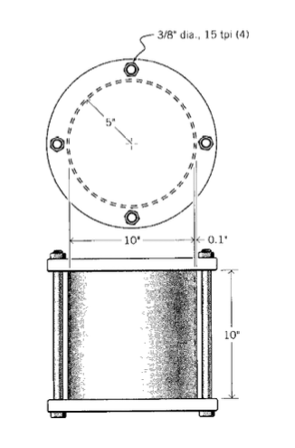
As pressure \(p\) inside the cylinder increases, a force \(F = p(\pi R^2)\) is exerted on the end plates, and this is reacted equally by the four restraining bolts; each thus feels a force \(F_b\) given by
\[F_b = \dfrac{p(\pi R^2)}{4}\nonumber\]
The bolts then stretch by an amount \(\delta_b\) given by:
\[\delta_b = \dfrac{F_b L}{A_b E_b}\nonumber\]
It’s tempting to say that the vessel will start to leak when the bolts have stretched by an amount equal to the original tightening; i.e. 1/2 turn/15 turns per inch. But as \(p\) increases, the cylinder itself is deforming as well; it experiences a radial expansion according to Equation 2.2.4. The radial expansion by itself doesn’t cause leakage, but it is accompanied by a Poisson contraction \(\delta_c\) in the axial direction. This means the bolts don’t have to stretch as far before the restraining plates are lifted clear. (Just as leakage begins, the plates are no longer pushing on the cylinder, so the axial loading of the plates on the cylinder becomes zero and is not needed in the analysis.)
The relations governing leakage, in addition to the above expressions for \(\delta_b\) and \(F_b\) are therefore:
\[\delta_b + \delta_c = \dfrac{1}{2} \times \dfrac{1}{15}\nonumber\]
where here the subscripts \(b\) and \(c\) refer to the bolts and the cylinder respectively. The axial deformation \(\delta_c\) of the cylinder is just \(L\) times the axial strain \(\epsilon_z\), which in turn is given by an expression analogous to Equation 2.2.7:
\[\delta_c = \epsilon_z L = \dfrac{L}{E_c} [\sigma_z - \nu \sigma_{\theta}]\nonumber\]
Since \(\sigma_z\) becomes zero just as the plate lifts off and \(\sigma_{\theta} = pR/b_c\), this becomes
\[\delta_c = \dfrac{L}{E_c} \dfrac{\nu p R}{b_c}\nonumber\]
Combining the above relations and solving for \(p\), we have
\[p = \dfrac{2A_b E_b E_c b_c}{15RL (\pi R E_c b_c + 4 \nu A_b E_b)}\nonumber\]
On substituting the geometrical and materials numerical values, this gives
\[p = 496 \text{ psi}\nonumber\]
The Poisson’s ratio is a dimensionless parameter that provides a good deal of insight into the nature of the material. The major classes of engineered structural materials fall neatly into order when ranked by Poisson’s ratio:
| Material Class | Poisson's Ratio \(\nu\) |
| Ceramics | 0.2 |
| Metals | 0.3 |
| Plastics | 0.4 |
| Rubber | 0.5 |
(The values here are approximate.) It will be noted that the most brittle materials have the lowest Poisson’s ratio, and that the materials appear to become generally more flexible as the Poisson’s ratio increases. The ability of a material to contract laterally as it is extended longitudinally is related directly to its molecular mobility, with rubber being liquid-like and ceramics being very tightly bonded.
The Poisson’s ratio is also related to the compressibility of the material. The bulk modulus \(K\), also called the modulus of compressibility, is the ratio of the hydrostatic pressure \(p\) needed for a unit relative decrease in volume \(\Delta V/V\):
\[K = \dfrac{-p}{\Delta V/V}\]
where the minus sign indicates that a compressive pressure (traditionally considered positive) produces a negative volume change. It can be shown that for isotropic materials the bulk modulus is related to the elastic modulus and the Poisson’s ratio as
\[K = \dfrac{E}{3(1 - 2\nu)}\]
This expression becomes unbounded as ν approaches 0.5, so that rubber is essentially incompressible. Further, \(\nu\) cannot be larger than 0.5, since that would mean volume would increase on the application of positive pressure. A ceramic at the lower end of Poisson’s ratios, by contrast, is so tightly bonded that it is unable to rearrange itself to “fill the holes” that are created when a specimen is pulled in tension; it has no choice but to suffer a volume increase. Paradoxically, the tightly bonded ceramics have lower bulk moduli than the very mobile elastomers.
Exercise \(\PageIndex{1}\)
A closed-end cylindrical pressure vessel constructed of carbon steel has a wall thickness of \(0.075''\), a diameter of \(6''\), and a length of \(30''\). What are the hoop and axial stresses \(\sigma_{\theta}, \sigma_z\) when the cylinder carries an internal pressure of 1500 psi? What is the radial displacement \(\delta_r\)?
Exercise \(\PageIndex{2}\)
What will be the safe pressure of the cylinder in the previous problem, using a factor of safety of two?
Exercise \(\PageIndex{3}\)
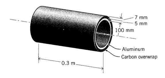
A compound pressure vessel with dimensions as shown is constructed of an aluminum inner layer and a carbon-overwrapped outer layer. Determine the circumferential stresses (\(\sigma_{\theta}\)) in the two layers when the internal pressure is 15 MPa. The modulus of the graphite layer in the circumferential direction is 15.5 GPa.
Exercise \(\PageIndex{4}\)
A copper cylinder is fitted snugly inside a steel one as shown. What is the contact pressure generated between the two cylinders if the temperature is increased by 10\(^{\circ} C\)? What if the copper cylinder is on the outside?
Exercise \(\PageIndex{5}\)
Three cylinders are fitted together to make a compound pressure vessel. The inner cylinder is of carbon steel with a thickness of 2 mm, the central cylinder is of copper alloy with a thickness of 4 mm, and the outer cylinder is of aluminum with a thickness of 2 mm. The inside radius of the inner cylinder is 300 mm, and the internal pressure is 1.4 MPa. Determine the radial displacement and circumfrential stress in the inner cylinder.
Exercise \(\PageIndex{6}\)
A pressure vessel is constructed with an open-ended steel cylinder of diameter \(6''\), length \(8''\), and wall thickness \(0.375''\). The ends are sealed with rigid end plates held by four \(1/4''\) diameter bolts. The bolts have 18 threads per inch, and the retaining nuts have been tightened 1/4 turn beyond their just-snug point before pressure is applied. Find the internal pressure that will just cause incipient leakage from the vessel.
Exercise \(\PageIndex{7}\)
An aluminum cylinder, with \(1.5''\) inside radius and thickness \(0.1''\), is to be fitted inside a steel cylinder of thickness \(0.25''\). The inner radius of the steel cylinder is \(0.005''\) smaller than the outer radius of the aluminum cylinder; this is called an interference fit. In order to fit the two cylinders together initially, the inner cylinder is shrunk by cooling. By how much should the temperature of the aluminum cylinder be lowered in order to fit it inside the steel cylinder? Once the assembled compound cylinder has warmed to room temperature, how much contact pressure is developed between the aluminum and the steel?
Exercise \(\PageIndex{8}\)
Assuming the material in a spherical rubber balloon can be modeled as linearly elastic with modulus \(E\) and Poisson’s ratio \(\nu = 0.5\), show that the internal pressure \(p\) needed to expand the balloon varies with the radial expansion ratio \(\lambda_r = r/r_0\) as
\[\dfrac{pr_0}{4Eb_0} = \dfrac{1}{\lambda_r^2} - \dfrac{1}{\lambda_r^3}\nonumber\]
where \(b_0\) is the initial wall thickness. Plot this function and determine its critical values.
Exercise \(\PageIndex{9}\)
Repeat the previous problem, but using the constitutive relation for rubber:
\[t\sigma_x =\dfrac{E}{3}\left (\lambda_x^2 - \dfrac{1}{\lambda_x^2 \lambda_y^2} \right )\nonumber\]
Exercise \(\PageIndex{10}\)
What pressure is needed to expand a balloon, initially \(3''\) in diameter and with a wall thickness of \(0.1''\), to a diameter of \(30''\)? The balloon is constructed of a rubber with a specific gravity of 0.9 and a molecular weight between crosslinks of 3000 g/mol. The temperature is \(20^{\circ}\).
Exercise \(\PageIndex{11}\)
After the balloon of the previous problem has been inflated, the temperature is increased by 25C. How do the pressure and radius change?