
1.3: Description of Strain in the Cylindrical Coordinate System
- Page ID
- 21471

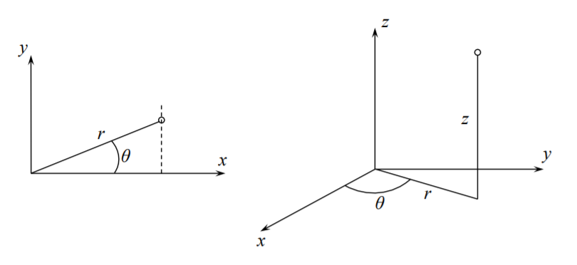
In this section the strain-displacement relations will be derived in the cylindrical coordinate system \((r, \theta, z)\).
The polar coordinate system is a special case with \(z = 0\). The components of the displacement vector are \(\{u_r, u_{\theta}, u_z\}\). There are two ways of deriving the kinematic equations. Since strain is a tensor, one can apply the transformation rule from one coordinate to the other. This approach is followed for example on pages 125-128 of the book on “A First Course in Continuum Mechanics” by Y.C. Fung. Or, the expression for each component of the strain tensor can be derived from the geometry. The latter approach is adopted here. The diagonal (normal) components \(\epsilon_{rr}\), \(\epsilon_{\theta\theta}\), and \(\epsilon_{zz}\) represent the change of length of an infinitesimal element. The non-diagonal (shear) components describe the change of angles.
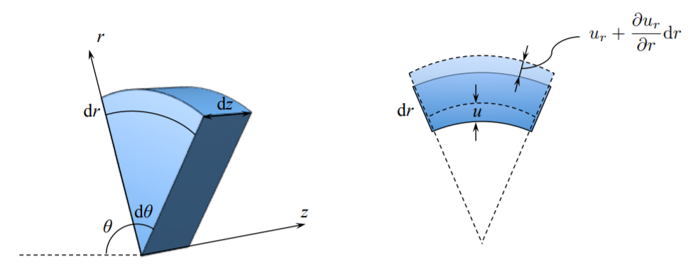
The radial strain is solely due to the presence of the displacement gradient in the \(r\)-direction
\[\epsilon_{rr} = \frac{ \left\{ u_r + \frac{\partial u_r}{\partial r} d r - u_r \right\} }{ d r} = \frac{\partial u_r}{\partial r}\]
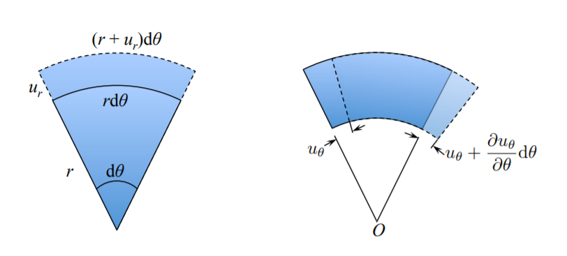
The circumferential strain has two components
\[\epsilon_{\theta\theta} = \epsilon_{\theta\theta}^{(1)} + \epsilon_{\theta\theta}^{(2)}\]
The first component is the change of length due to radial displacement, and the second component is the change of length due to circumferential displacement.
From Figure (\(\PageIndex{3}\)) the components \(\epsilon_{\theta\theta}^{(1)}\) and \(\epsilon_{\theta\theta}^{(2)}\) are calculated as
\[\epsilon_{\theta\theta}^{(1)} = \frac{(r+u_r) d \theta - r d\theta}{r d \theta} = \frac{u_r}{r}\]
\[\epsilon_{\theta\theta}^{(2)} = \frac{u_{\theta} + \frac{\partial u_{\theta}}{\partial \theta} d \theta - u_{\theta} }{r d \theta} = \frac{1}{r}\frac{\partial u_{\theta}}{\partial \theta}\]
The total circumferential (hoop) component of the strain tensor is
\[\epsilon_{\theta \theta} = \frac{u_r}{r} + \frac{1}{r} \frac{\partial u_{\theta}}{\partial d \theta}\]
The strain components in the \(z\)-direction is the same as in the rectangular coordinate system
\[\epsilon_{zz} = \frac{\partial u_z}{\partial z}\]
The shear strain \(\epsilon_{r\theta}\) describes a change in the right angle.
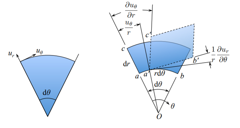
From Figure (\(\PageIndex{4}\)) the shear strain over the \(\{r, \theta\}\) plane is
\[\epsilon_{r \theta} = \frac{1}{2} \left[ \frac{\partial u_{\theta}}{\partial r} - \frac{u_{\theta}}{r} + \frac{1}{r}\frac{\partial u_r}{\partial \theta} \right]\]
On the \(\{r, z\}\) plane, the \(\epsilon_{rz}\) shear develops from the respective gradients, see Figure (\(\PageIndex{5}\)).
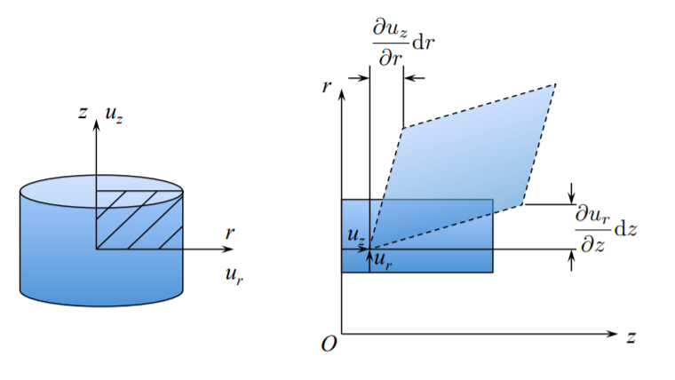
From the construction in Figure (\(\PageIndex{4}\)), the component \(\epsilon_{rz}\) is
\[\epsilon_{rz} = \frac{1}{2} \left( \frac{\partial u_r}{\partial z}+ \frac{\partial u_z}{\partial r}\right)\]
Finally, a similar picture is valid on the (tangent) \(\{z, \theta\}\) plane
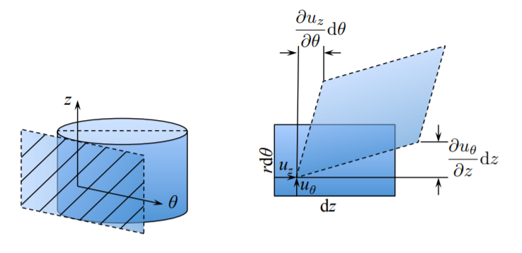
The component \(\epsilon_{\theta z}\) of the strain tensor is one half of the change of angles, i.e.
\[\epsilon_{\theta z} = \frac{1}{2} \left( \frac{\partial u_z}{r \partial \theta} + \frac{\partial u_{\theta}}{\partial z}\right)\]
To sum up the derivation, the six components of the infinitesimal strain tensor in the cylindrical coordinate system are
\[\epsilon_{rr} = \frac{\partial u_r}{\partial r} \]
\[\epsilon_{\theta \theta} = \frac{u_r}{r} + \frac{1}{r} \frac{\partial u_{\theta}}{\partial \theta}\]
\[\epsilon_{zz} = \frac{\partial u_x}{\partial z}\]
\[\epsilon_{r \theta} = \epsilon_{\theta r} = \frac{1}{2} \left( \frac{1}{r}\frac{\partial u_r}{\partial \theta} + \frac{\partial u_{\theta}}{\partial r} - \frac{u_{\theta}}{r}\right)\]
\[\epsilon_{\theta z} = \epsilon_{z \theta} = \frac{1}{2} \left( \frac{\partial u_z}{r \partial \theta}+ \frac{\partial u_{\theta}}{\partial z}\right)\]
\[\epsilon_{zr} = \epsilon_{rz} = \frac{1}{2} \left( \frac{\partial u_r}{\partial z}+ \frac{\partial u_z}{\partial r}\right)\]
Considerable simplifications are obtained in the case of axial (rotational symmetry for which \(u_{\theta} = 0\) and \(\frac{\partial}{\partial \theta} [\,] = 0\)
\[\epsilon_{rr} = \frac{\partial u_r}{\partial r} \quad \epsilon_{r \theta} = 0\]
\[\epsilon_{\theta \theta} = \frac{u_r}{r} \quad \epsilon_{\theta z} = 0\]
\[\epsilon_{zz} = \frac{\partial u_z}{\partial z} \quad \epsilon_{zr} = \frac{1}{2} \left( \frac{\partial u_r}{\partial z}+ \frac{\partial u_z}{\partial r}\right)\]
The application of the above geometrical relations for axi-symmetric loading of circular plates and cylindrical shells will be given in subsequent chapters.