4.3: Statically Determined Beams
- Page ID
- 21492

Beam for which the distribution of bending moments and shear forces can be determined from the equilibrium alone are called statically determinate beams. For such beams \(M(x)\) and \(V (x)\) are known and determination of beam deflection will be a much easier task. Combining Equation (4.1.9) with Equation (4.1.2) one ends up with the following second order linear differential equation
\[−EI \frac{d^2w}{dx^2} = M(x) \label{4.3.1}\]
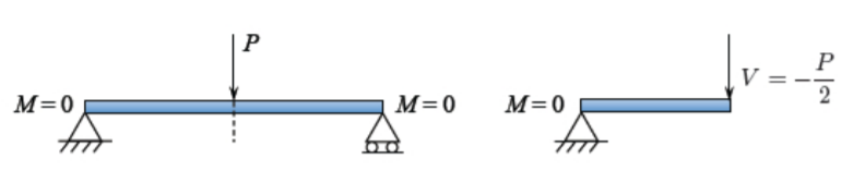
The bending moment, which by itself should satisfy the second order differential equation, Equation (4.1.7) should now obey two stress boundary conditions at the beam ends. The static boundary conditions are indicated in Figure (\(\PageIndex{1}\)) for a pin-pin supported and cantilever beam.
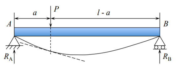
Determination of bending moment and shear force diagrams is the subject of elementary courses in statics, and the general procedure is not explained here. In the case of the simply supported beam with a point load at the mid-span, the bending moments
\[M(x) = \begin{cases} \frac{P x}{2} , & 0 < x < \frac{l}{2} \\ \frac{P(l − x)}{2} , & \frac{l}{2} < x < l \end{cases} \label{4.3.2}\]
The bending moment vanishes at \(x = 0\) and \(x = l\).
The corresponding shear force \(V = \frac{dM}{dx}\) is
\[V(x) = \begin{cases} \frac{P}{2} , & 0 < x < \frac{l}{2} \\ - \frac{P}{2} , & \frac{l}{2} < x < l \end{cases} \]
At the beam center
\[[V ] = \frac{P}{2} − \left[ − \frac{P}{2} \right] = P\]
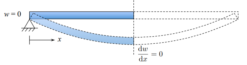
Because of shear force discontinuity at the beam center, the solution will be sought for a half of the beam. Each half of the beam is carrying half of the load. We have shown that the bending moment distribution satisfy two satin boundary condition. Therefore the differential equation \ref{4.3.2} is subjected only to two kinematic boundary conditions
Integrating Equation \ref{4.3.1} twice one gets
\[−EIw = \frac{P x^3}{12} + C_1x + C_2\]
The two integration constants, determined from the boundary conditions \(w(0) = 0, \quad \left. \frac{dw}{dx} \right|_{ x= \frac{l}{h}} = 0\), are
\[C_1 = −\frac{Pl^2}{16}, \quad C_2 = 0\]
and the deflection line of the beam is given by
\[w(x) = \frac{Px}{48EI} (3l^2 - 4x^2) \quad 0 < x < \frac{l}{2}\]
The second half of the beam is the mirror reflection, by symmetry. In particular, the central deflection \(w_o = w(x = \frac{l}{2})\) is expressed by all input parameters of the beam as
\[w_o = \frac{Pl^3}{48EI}\]
It will be helpful to remember the above formula for the rest of your professional life.
In summary, determination of deflections of statically determinate beams is much easier than its statically indeterminate counterparts. The governing equation is of the second order, and for symmetric problems there are only two integration constants.