6.6: Stiffened Plates
- Page ID
- 21509

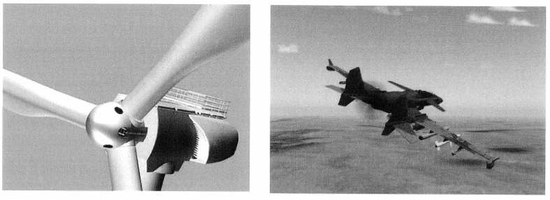
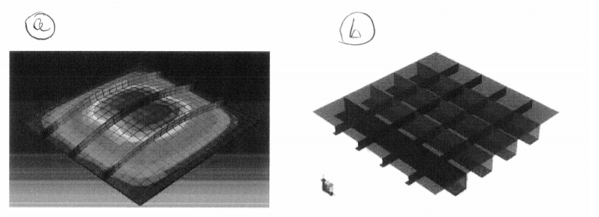
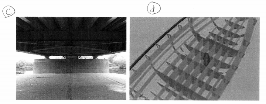
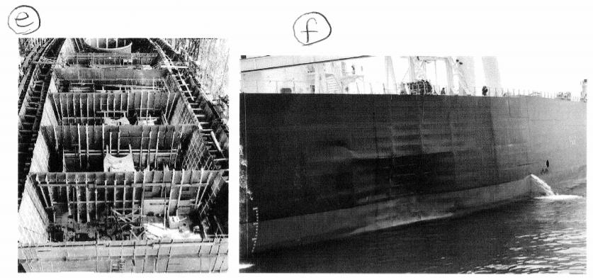
Another way of light weighting plates is to provide a system of uni-directional or orthogonal stiffeners. As opposed to sandwich structures which are symmetric, stiffened plates are asymmetric with the neutral axis positioned usually outside the profile of the plate. A stiffened plates consists of a system of beams interacting with a uniform thickness plate. Photos of typical stiffened plates used in civil engineering, ship buildings and other segment of the economy are shown in Figure (\(\PageIndex{2}\)).
© sources unknown. All rights reserved. This content is excluded from our Creative Commons license. For more information, see http://ocw.mit.edu/help/faq-fair-use/.
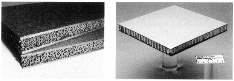
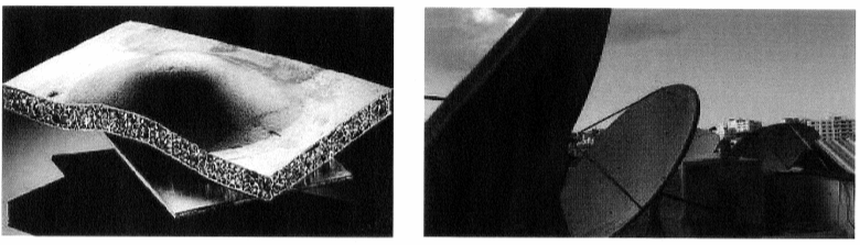
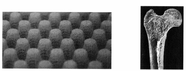
Figure \(\PageIndex{1}\): Pictures of foam-filled and honeycomb core sandwich plates and panels with some applications.
© sources unknown. All rights reserved. This content is excluded from our Creative Commons license. For more information, see http://ocw.mit.edu/help/faq-fair-use/.
Figure \(\PageIndex{2}\): Stiffened panels are fundamental building blocks of modern structures.
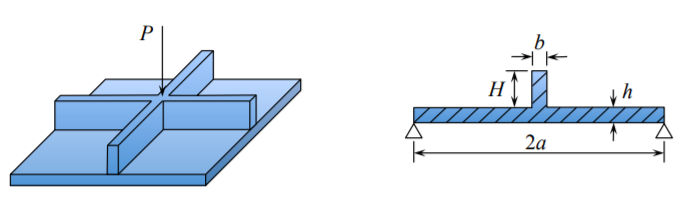
To illustrate the response of stiffened plates to transverse loads consider an example of a simply supported plate stiffened by two cross-beams, Figure (\(\PageIndex{3}\)).
The structure is loaded by a point force \(P\) at the center. For simplicity, shown is the simplest flat bar stiffener but the analysis is valid for any beam defined by the moment of inertia \(I\). Can we determine the stiffness of the system using our existing knowledge of beams and plates? Let’s see.
The solution for the beam problem is
\[w(x) = w^b_o\frac{x}{l} \left[3 − 4 \left(\frac{x}{l}\right)^2\right] \label{7.56a}\]
\[w^b_o = \frac{P^b l^3}{48EI} \label{7.56b}\]
where \(l = 2a\) is the length of the stiffener. The solution for the circular plate under the concentrated point load is given by Equation (6.2.16)
\[\bar{w} = \frac{w(r)}{w^p_o} = \left[ 2 \left( \frac{r}{a} \right)^2 \ln \frac{r}{a} + \frac{3 + \nu}{1+ \nu} \left( 1- \left( \frac{r}{a}\right)^2 \right) \right] \label{7.57a} \]
\[w^p_o = \frac{p^p a^2}{16 \pi D} \label{7.57b} \]
Here the analogy between the response of a circular and square plate was used with \(a \approx R\).
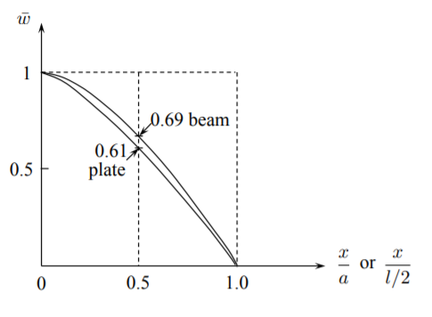
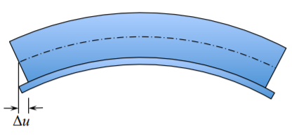
The comparison of the deflected shapes of the beam and the plate is shown in Figure (\(\PageIndex{4}\)). This means that in terms of vertical deflections \(w\) the beam shape fits on the deform plate. What about the horizontal displacements? This is shown in Figure (\(\PageIndex{5}\)). The beam and the plate deform separately and there is an incompatibility of the displacement \(u\). This corresponds to the situation that both components are not connected, with sliding allowed. Should sliding be prevented, for example by welding, the neutral axis of the plate-beam combination will be shifted. Therefore the actual stiffness of the welded stiffen structure will be greater than simply adding their individual contributions. The present model will give only the lower bound. Let’s calculate the lower bound stiffness of the system.
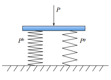
The almost perfect compatibility of the vertical displacement, shown in Figure (\(\PageIndex{4}\)), means that we are dealing with two linear springs in parallel, Figure (\(\PageIndex{6}\)). The total resisting force is the sum of individual components, while the displacements are the same
\[P = P_p + P_b; \quad w^p_o = w^b_o = w_o\]
From Equations \ref{7.56a} - \ref{7.56b} and \ref{7.57a} - \ref{7.57b} one gets
\[P = \left( \frac{16 \pi D}{a^2} + \frac{6EI}{a^3} \right) w_o \label{7.59}\]
If we assume for simplicity that the flat bar stiffener is of the same thickness as the plate, \(b = h\), then Equation \ref{7.59} simplifies to
\[P = \frac{1}{2} Ehw_o \left[ \frac{8\pi}{3(1-\nu^2)} \left( \frac{h}{a}\right)^2 + \left(\frac{H}{a}\right)^3\right]\]
To get a feel, the plate and beam will equally contribute to the stiffen of the system if
\[\left( \frac{3h}{a}\right)^2 = \left(\frac{H}{a}\right)^3\]
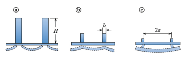
For a typical plate with span to thickness ratio \(a/h = 30\), the hight of the stiffener is \(H \cong 0.2a\). How good the above lower bound solution is? This is a difficult question to which no general and simple solution can be derived.
It is helpful to distinguish three limiting cases shown in Figure (\(\PageIndex{7}\)). A very substantial and sparsely positioned stiffeners acts as an almost rigid clamped support to the plate, case (a). Light and densely distributed stiffeners, case (c), deform together with the plate. there is one deflection line and stiffeners contribute to the bending stiffness of the plate. The case (b) is a combination of the above two extreme cases. Cases (a) and (c) will be studied below.