
2.3.4: Kirchhoff's Current Law
- Page ID
- 52893

Just as Kirchhoff's voltage law is a key element in understanding series circuits, Kirchhoff's current law (KCL) is the operative rule for parallel circuits. It states that the sum of all currents entering and exiting a node must sum to zero. Alternately, it can be stated as the sum of currents entering a node must equal the sum of currents exiting that node. As a pseudo formula:
\[\sum I \rightarrow = \sum I \leftarrow \label{4.6} \]
Recalling that a node is a connection area wherein the voltage is the same (ignoring the resistance of connecting wires), we see that there are two nodes in a parallel configuration. For each of these nodes, whatever currents flow in must be balanced by the same total current flowing out. For example, referring to the circuit shown in Figure 4.4.1 , there is a current source feeding the top node. At the three-way connection with \(R_1\) and \(R_2\), KCL along with Ohm's law dictate that the incoming current from the source must split with one portion exiting by flowing down through \(R_1\) and the remainder exiting by flowing down through \(R_2\). At the bottom node (ground) these two resistor currents must combine and equal the current that is being drawn back into the current source, which must be the same as the current originally produced by the source. This is perfectly sensible because it would be impossible for the current source to establish two different currents; one at its input and the other at its output. To assert otherwise would be a little like saying you're two different heights depending on whether you measure from your toes up to your head versus from your head down to your toes. Thus, a simplistic way of stating KCL is “What goes in must come out”.1
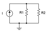
Figure 4.4.1 : A simple parallel circuit.
The Current Divider Rule (CDR)
Just as series circuits follow the voltage divider rule (voltage dividing in proportion to resistance), parallel circuits follow the current divider rule which states that current divides in reverse proportion to resistance (i.e., in direct proportion to conductance). This can be reduced to a simple formula when only two resistors are involved. Consider two parallel resistors, \(R_1\) and \(R_2\), fed by a current, \(I_{Total}\), as in Figure 4.4.1 . First, we note that the voltage across the pair must equal the entering current times the effective resistance of the pair.
\[V = I_{Total} \frac{R_1R_2}{R_1+R_2} \nonumber \]
The current through each of the resistors must be this voltage divided by the corresponding resistance. For the current through \(R_1\):
\[I_{R1} = \frac{V}{R_1} \nonumber \]
\[I_{R1} = I_{Total} \frac{R_1 R_2}{R_1 (R_1+R_2 )} \nonumber \]
\[I_{R1} = I_{Total} \frac{R_2}{R_1+R_2} \nonumber \]
Similarly, for the current through \(R_2\):
\[I_{R2} = \frac{V}{R_2} \nonumber \]
\[I_{R2} = I_{Total} \frac{R_1 R_2}{R_2 (R_1+R_2 )} \nonumber \]
\[I_{R2} = I_{Total} \frac{R_1}{R_1+R_2} \nonumber \]
Thus, the current through one of the resistors will equal the total current times the ratio of the opposite resistor over the sum of the two resistors. In general:
\[I_X = I_{Total} \frac{R_Y}{R_X+R_Y} \label{4.7} \]
This rule is convenient in that you don't have to compute the parallel equivalent resistance, but remember, it is valid only when there are just two resistors involved. A more general version that can be used for any number of resistors is \(I_i = I_{Total} \cdot R_P/R_i\), where \(R_P\) is the total equivalent parallel resistance and \(R_i\) is the resistor of interest. This is, in essence, merely a rewriting of the fact that all components must see the same voltage: \(I_i \cdot R_i = I_{Total} \cdot R_P\). This is not as much of a shortcut as the two resistor version because the parallel resistance still must be calculated.
A simple parallel network is shown in Figure 4.4.2 . Determine the current through each resistor.
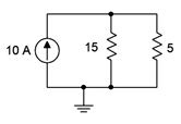
Figure 4.4.2 : Circuit for Example 4.4.1 .
The current divider rule can be used to find the currents through the two resistors. At the top node the total entering current is 10 amps.
\[I_{R1} = I_{Total} \frac{R_2}{R_1+R_2} \nonumber \]
\[I_{15} = 10 A \frac{5 \Omega }{15 \Omega +5 \Omega } \nonumber \]
\[I_{15} = 2.5 A \nonumber \]
\[I_{R2} = I_{Total} \frac{R_1}{R_1+R_2} \nonumber \]
\[I_{5} = 10 A \frac{15 \Omega }{15 \Omega +5 \Omega } \nonumber \]
\[I_{5} = 7.5 A \nonumber \]
At this point it is worth taking a moment to verify the voltage polarities and current directions. Given the direction of the source, the currents through the two resistors must be flowing from top to bottom. Consequently, the voltage polarities must be + to − from top to bottom. This is illustrated in Figure 4.4.3 . At the top node, entering current is in red with exiting current in blue. Note that KCL is satisfied as 10 amps enters while a total of 10 amps (2.5 amps plus 7.5 amps) exits.
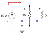
Figure 4.4.3 : Polarities and directions for Example 4.4.1 .
References
1For details on this corollary to Fudd's First Law of Opposition, see Firesign Theatre, I Think We're All Bozos On This Bus. Remember, the future can't wait.