
2.3.6: Current Limiting - Fuses and Circuit Breakers
- Page ID
- 52895

Most electrical and electronic devices are designed to run off of a constant voltage source. Examples include battery powered devices and the numerous items that connect to standard residential and commercial electrical systems (e.g., the 120 VAC system in North America). As such, parallel connections are ideal when a variable number of devices are to be powered because, unlike a series connection, each device will see the same voltage rather than having that voltage split among them. There is another advantage to a parallel connection. Consider the two lighting schemes presented in Figure 4.6.1 ; one utilizing a series configuration and the other a parallel configuration.
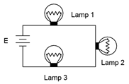
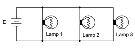
Figure 4.6.1 : Lamp connections: Series (left) and parallel (right).
Typically, when a lamp fails, it fails creating an open. If any of the lamps in the series connection fails, current in the loop is interrupted and all of the lamps go out. In contrast, if one of the lamps in the parallel connection fails, the remaining lights will stay on. Further, in the series connection, there is no immediate way to determine which lamp has failed as none of them will be lit. Each lamp has to be tested in turn to determine the faulty unit. In the parallel system, it is obvious which lamp has failed because that's the one that's out.
In a home, school or commercial setting, any number of devices may be plugged into wall sockets with the expectation that each unit will receive the same voltage and operate correctly due to the parallel nature of the system. As convenient as this is, there is a practical problem. Every device that is added to the system presents another path for current flow. Due to KCL, this means that the total current drawn from the source must increase. This creates a potential problem because if too much current is drawn, there can be an appreciable voltage drop across the wires feeding the outlets as they can no longer be assumed to be zero ohms. This lowered voltage may present a problem for the attached devices, but more importantly, the large current results in unexpected heating of the wires because of the power dissipation in them (I\(^2\)R) and creates a possible fire hazard. Consequently, we must include some method to limit the current to a safe maximum value.
While some electronic systems use active current limiting schemes1, the more common approach is a fuse or circuit breaker. These devices are placed between the voltage source and the various loads, and see their combined current. If this current becomes too great, the device interrupts the current flow by opening the circuit. Nothing will operate but nothing catches fire, either. Fuses are used typically in electronic systems, motors, automotive subsystems and the like. An array of various types of fuses is shown in Figure 4.6.2 . Whether they're the cylindrical type found in electronic instrumentation or the blade type common in automobiles, fuses are one-shot devices. They consist of a fine wire or metal link that will heat up and melt if it experiences too high of a current. Upon melting, circuit continuity is lost and current flow stops. This is called a “blown” fuse. The fuse will then need to be replaced once the problem has been fixed (i.e., whatever it was that caused excessive current to flow in the first place).
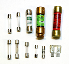
Figure 4.6.2 : Various styles of fuses.
Fuses have a nominal current rating, for example, two amps. This does not mean that as soon as two amps is reached, the fuse blows. It will take some time for the fuse to heat up. The higher the current is above the nominal rating, the faster the fuse will blow. For example, it might take this nominal two amp fuse several seconds before it blows if the current is, say, 2.5 amps, but less than a second if the current is five amps. Fuses are also available in fast-blow and slow-blow forms. Fast-blow fuses will activate many times faster than standard fuses while slow-blow types will require much long to activate (this prevents the fuse from activating accidentally with certain kinds of loads that exhibit a high initial startup current but that falls back to a more modest level once running smoothly, such as a motor). The schematic symbols for the fuse are shown in Figure 4.6.3 . The top two are IEC standard and the bottom version is the ANSI (North American) standard.
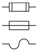
Figure 4.6.3 : Schematic symbols for fuses: IEC (top and middle), ANSI (bottom).
Fuses are generally inexpensive and effective. The obvious downside to a fuse is that they need to be replaced once they do their job. A circuit breaker solves this problem. A circuit breaker, or just breaker for short, can be thought of as a resettable fuse. Breakers do not have a melting link that interrupts current flow. Instead, a breaker operates like an intelligent switch: if the current is too large, the switch is thrown open. The operator can then fix the problem and reset the breaker (i.e., return the switch to the operating position). A selection of breakers is shown in Figure 4.6.4 . Circuit breakers are available in a variety of sizes. For residential wiring, 15 and 20 amp sizes are common for general use although higher sizes such as 30 and 50 amps are available for circuits feeding high power appliances such as electric stoves, water heaters and clothes dryers.
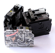
Figure 4.6.4 : Residential circuit breakers including cutaway view.
References
1For details, see Fiore, J., Semiconductor Devices as well as Operational Amplifiers and Linear Integrated Circuits, both OER titles.