
2.4.6: Exercises
- Page ID
- 52904

Analysis
1. In the circuit of Figure 5.6.1 , which individual resistors are strictly in series and which are in parallel?
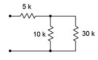
Figure 5.6.1
2. In the circuit of Figure 5.6.2 , which individual resistors are strictly in series and which are in parallel?
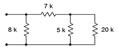
Figure 5.6.2
3. In the circuit of Figure 5.6.3 , which individual resistors are strictly in series and which are in parallel?
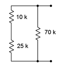
Figure 5.6.3
4. In the circuit of Figure 5.6.4 , which individual resistors are strictly in series and which are in parallel?
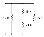
Figure 5.6.4
5. In the circuit of Figure 5.6.5 , which individual resistors are strictly in series and which are in parallel?
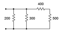
Figure 5.6.5
6. In the circuit of Figure 5.6.6 , which individual resistors are strictly in series and which are in parallel?
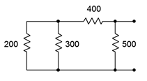
Figure 5.6.6
7. In the circuit of Figure 5.6.7 , which individual resistors are strictly in series and which are in parallel?
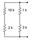
Figure 5.6.7
8. In the circuit of Figure 5.6.8 , which individual resistors are strictly in series and which are in parallel?
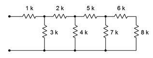
Figure 5.6.8
9. Determine the equivalent resistance of the network shown in Figure 5.6.1 (i.e., as if an ohmmeter is connected to the two terminals).
10. Determine the equivalent resistance of the network shown in Figure 5.6.2 .
11. Determine the equivalent resistance of the network shown in Figure 5.6.3 .
12. Determine the equivalent resistance of the network shown in Figure 5.6.4 .
13. Determine the equivalent resistance of the network shown in Figure 5.6.5 .
14. Determine the equivalent resistance of the network shown in Figure 5.6.6 .
15. Determine the equivalent resistance of the network shown in Figure 5.6.7 .
16. Determine the equivalent resistance of the network shown in Figure 5.6.8 .
17. For the circuit of Figure 5.6.9 , find voltages \(V_a\), \(V_b\) and \(V_{ab}\).
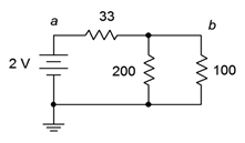
Figure 5.6.9
18. For the circuit of Figure 5.6.9 , find the current through each resistor.
19. For the circuit of Figure 5.6.10 , find the current through each resistor.
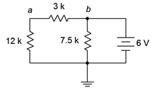
Figure 5.6.10
20. For the circuit of Figure 5.6.10 , find voltages \(V_a\), \(V_b\) and \(V_{ab}\).
21. For the circuit of Figure 5.6.11 , find voltages \(V_a\), \(V_b\) and \(V_{ab}\).
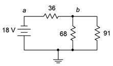
Figure 5.6.11
22. For the circuit of Figure 5.6.11 , find the current through each resistor.
23. For the circuit of Figure 5.6.12 , find the current through each resistor.
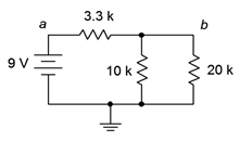
Figure 5.6.12
24. For the circuit of Figure 5.6.12 , find voltages \(V_a\), \(V_b\) and \(V_{ab}\).
25. In the circuit of Figure 5.6.13 , find voltages \(V_a\), \(V_b\) and \(V_{ab}\).
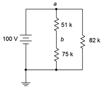
Figure 5.6.13
26. In the circuit of Figure 5.6.13 , find the current through each resistor.
27. In the circuit of Figure 5.6.14 , find the current through each resistor.
28. In the circuit of Figure 5.6.14 , find voltages \(V_a\), \(V_b\) and \(V_{ab}\).
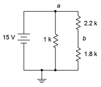
Figure 5.6.14
29. For the circuit of Figure 5.6.15 , find voltages \(V_b\), \(V_c\) and \(V_{cb}\).
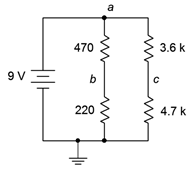
Figure 5.6.15
30. For the circuit of Figure 5.6.15 , find the current through the 470 \(\Omega\) and 3.6 k\(\Omega\) resistors along with the source current.
31. For the circuit of Figure 5.6.16 , find the current through the 2 k\(\Omega\) and 5.1 k\(\Omega\) resistors along with the source current.
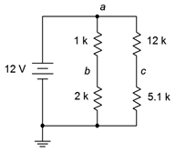
Figure 5.6.16
32. For the circuit of Figure 5.6.16 , find voltages \(V_c\), \(V_b\), \(V_{bc}\) and \(V_{ab}\).
33. For the circuit of Figure 5.6.17 , find voltages \(V_a\) and \(V_b\).
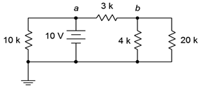
Figure 5.6.17
34. For the circuit of Figure 5.6.17 , find the current through the 10 k\(\Omega\) and 4 k\(\Omega\) resistors along with the source current.
35. For the circuit of Figure 5.6.18 , find the current through the 30 k\(\Omega\) and the left-most 36 k\(\Omega\) resistors along with the source current.
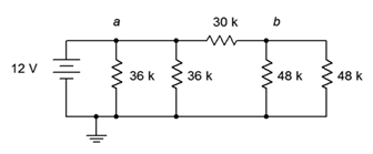
Figure 5.6.18
36. For the circuit of Figure 5.6.18 , find voltages \(V_a\), \(V_b\) and \(V_{ab}\).
37. In the circuit of Figure 5.6.18 , must the currents through the two 36 k\(\Omega\) resistors be the same? Why/why not?
38. In the circuit of Figure 5.6.18 , must the currents through the two 48 k\(\Omega\) resistors be the same? Further, must these currents be the same as the currents through the two 36 k\(\Omega\) resistors Why/why not?
39. For the circuit of Figure 5.6.19 , find voltages \(V_a\), \(V_b\) and \(V_{ab}\).
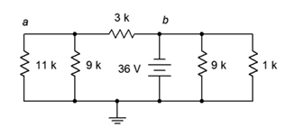
Figure 5.6.19
40. For the circuit of Figure 5.6.19 , find the current through the 3 k\(\Omega\), 11 k\(\Omega\), and both 9 k\(\Omega\) resistors.
41. Given the circuit of Figure 5.6.20 , find the current through the 47 k\(\Omega\), 5.1 k\(\Omega\), and 3.9 k\(\Omega\) resistors.
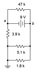
Figure 5.6.20
42. Given the circuit of Figure 5.6.20 , find voltages \(V_a\), \(V_b\) and \(V_{ab}\).
43. For the circuit of Figure 5.6.21 , find voltages \(V_b\), \(V_c\) and \(V_d\).
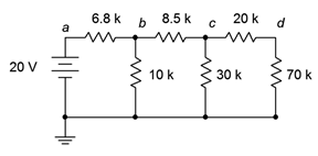
Figure 5.6.21
44. For the circuit of Figure 5.6.21 , find the current through the 6.8 k\(\Omega\), 8.5 k\(\Omega\), and 20 k\(\Omega\) resistors.
45. The circuit of Figure 5.6.22 is called an R-2R ladder. Find the current through each of the 60 k\(\Omega\) resistors.
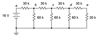
Figure 5.6.22
46. Given the circuit of Figure 5.6.22 , find voltages \(V_b\), \(V_c\), \(V_d\) and \(V_e\). What is unique about this configuration?
47. For the circuit of Figure 5.6.23 , find voltages \(V_a\), \(V_b\) and \(V_{ab}\).
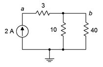
Figure 5.6.23
48. For the circuit of Figure 5.6.23 , find the current through each of the resistors.
49. For the circuit of Figure 5.6.24 , find the current through each of the resistors.
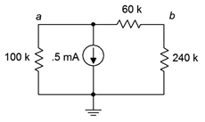
Figure 5.6.24
50. For the circuit of Figure 5.6.24 , find voltages \(V_a\), \(V_b\) and \(V_{ab}\).
51. Given the circuit of Figure 5.6.25 , find voltages \(V_a\), \(V_b\) and \(V_{ab}\).
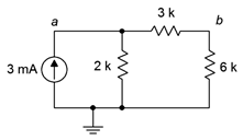
Figure 5.6.25
52. Given the circuit of Figure 5.6.25 , find the current through each of the resistors.
53. For the circuit of Figure 5.6.26 , find the current through the 200 \(\Omega\), 400 \(\Omega\), and 100 \(\Omega\) resistors.
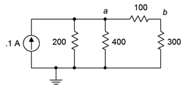
Figure 5.6.26
54. For the circuit of Figure 5.6.26 , find voltages \(V_a\), \(V_b\) and \(V_{ab}\).
55. Given the circuit of Figure 5.6.27 , find voltages \(V_a\), \(V_b\) and \(V_{ab}\).
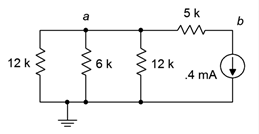
Figure 5.6.27
56. Given the circuit of Figure 5.6.27 , find the current through the 5 k\(\Omega\), and 6 k\(\Omega\) resistors.
57. For the circuit of Figure 5.6.28 , find the current through the 9 k\(\Omega\) and rightmost 82 k\(\Omega\) resistors.
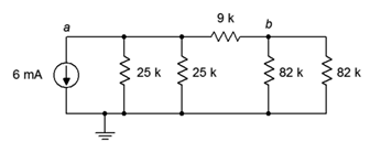
Figure 5.6.28
58. For the circuit of Figure 5.6.28 , find voltages \(V_a\), \(V_b\) and \(V_{ab}\).
59. Must the current through the 82 k\(\Omega\) resistors be identical in the circuit of 4.8.6? Why/why not?
60. Must the current through the 25 k\(\Omega\) resistors be identical in the circuit of 4.8.6? Must they be the same as the currents through the 82 k\(\Omega\) resistors? Why/why not?
61. For the circuit of Figure 5.6.29 , find voltages \(V_a\), \(V_b\) and \(V_{ab}\).
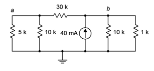
Figure 5.6.29
62. For the circuit of Figure 5.6.29 , find the current through the 30 k\(\Omega\), 5 k\(\Omega\), and 1 k\(\Omega\) resistors.
63. For the circuit of Figure 5.6.30 , find the current through the 1 k\(\Omega\), 2.2 k\(\Omega\), and 18 k\(\Omega\) resistors.
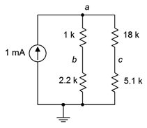
Figure 5.6.30
64. For the circuit of Figure 5.6.30 , find voltages \(V_a\), \(V_b\) and \(V_c\).
65. Given the circuit of Figure 5.6.31 , find voltages \(V_a\), \(V_b\) and \(V_{ab}\).
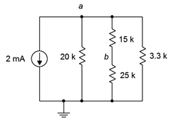
Figure 5.6.31
66. Given the circuit of Figure 5.6.31 , find the current through the 20 k\(\Omega\), 15 k\(\Omega\), and 3.3 k\(\Omega\) resistors.
67. The circuit of Figure 5.6.32 is referred to as an R-2R ladder network. Find the current through each of the 4 k\(\Omega\) resistors.
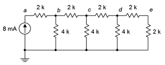
Figure 5.6.32
68. For the circuit of Figure 5.6.32 , find voltages \(V_a\), \(V_b\) and \(V_{ab}\). What is the unique characteristic of this configuration?
Design
69. Determine a new value for the 33 \(\Omega\) resistor in Figure 5.6.9 such that the source current is 10 mA.
70. Determine a new value for the 20 k\(\Omega\) resistor in Figure 5.6.12 such that \(V_b\) is 4 volts.
71. Determine a new value for the 470 \(\Omega\) resistor in Figure 5.6.15 such that \(V_b\) is 6 volts.
72. Determine a new value for the 1 k\(\Omega\) resistor in Figure 5.6.14 such that the source current is 20 mA.
73. Determine a new value for the 12 k\(\Omega\) resistor in Figure 5.6.16 such that \(V_{bc}\) is 0 volts.
74. Given the circuit of Figure 5.6.24 , determine a new value for the 100 k \(\Omega\) resistor such that \(V_a\) is 75 volts.
75. Given the circuit of Figure 5.6.23 , determine a new value for the current source such that \(V_b\) is 8 volts.
76. Determine a new value for the 2.2 k\(\Omega\) resistor in Figure 5.6.30 such that \(V_{bc}\) is 0 volts.
77. Given the circuit of Figure 5.6.32 , determine a new value for the current source such that \(V_e\) is 1 volt.
Challenge
78. Utilizing only 1 k\(\Omega\) resistors, create a series-parallel combination that achieves 1.25 k\(\Omega\) of total resistance.
79. Utilizing only 12 k\(\Omega\) resistors, create a series-parallel combination that achieves 9 k\(\Omega\) of total resistance.
80. Consider the circuit of Figure 5.6.22 . Alter the values of the two right-most 30 k\(\Omega\) resistors such that \(V_e\) is 1.2 volts. The remaining node voltages should be unchanged from the original circuit.
81. Alter the circuit shown in Figure 5.6.22 such that another “wrung” is added to the ladder creating a new right-most node \(f\). If the former terminating 30 k\(\Omega\) resistor (i.e., the vertical one) is reset to 60 k\(\Omega\), determine the values of the resistors on the new wrung such that \(V_f\) is 0.5 volts.
82. Given the circuit of Figure 5.6.25 , determine a new value for the 2 k \(\Omega\) resistor such that \(V_b\) is 12 volts.
83. Given the circuit of Figure 5.6.32 , determine new values for the resistors such that all of the node voltages are twice the value of the original circuit's node voltages.
Simulation
84. Perform a DC simulation on the result of problem 24 to verify the node voltages.
85. Perform a DC simulation on the result of problem 25 to verify the node voltages.
86. Perform a DC simulation on the result of problem 43 to verify the node voltages.
87. Perform a DC simulation on the result of problem 46 to verify the node voltages.
88. Perform a DC simulation on the result of problem 51 to verify the node voltages.
89. Perform a DC simulation on the result of problem 68 to verify the node voltages.
90. Perform a DC simulation on the proposed solution to problem 69 to verify the new design.
91. Perform a DC simulation of the alteration presented in Challenge problem 80. Does the new design meet all of the requirements?
92. Perform a DC simulation of the alteration requested in Challenge problem 83. Does the new design meet all of the requirements?