
7.11.8: Problems
- Page ID
- 53022

10.7.1: Review Questions
1. What is the basic function of an integrator?
2. What is the basic function of a differentiator?
3. What is the function of the capacitor in the basic integrator and differentiator?
4. Why are capacitors used in favor of inductors?
5. What practical modifications need to be done to the basic integrator, and why?
6. What practical modifications need to be done to the basic differentiator, and why?
7. What are the negative side effects of the practical versus basic integrator and differentiator?
8. What is an analog computer, and what is it used for?
9. What are some of the advantages and disadvantages of the analog computer versus the digital computer?
10. How might integrators and differentiators be used as wave-shaping circuits?
10.7.2: Problems
Analysis Problems
1. Sketch the output waveform for the circuit of Figure \(\PageIndex{1}\) if the input is a 4 V peak square wave at 1 kHz.
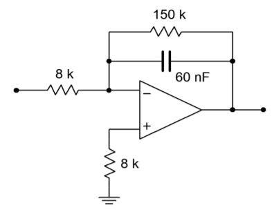
Figure \(\PageIndex{1}\)
2. Repeat Problem 1 if \(V_{in}(t) = 5 \sin 2 \pi 318t\).
3. Repeat Problem 1 if \(V_{in}(t) = 20 \cos 2 \pi 10000t\).
4. Using the circuit of Problem 1, if the input is a ramp with a slope of 10 V/s, find the output after 1 ms, 10 ms, and 4 s. Sketch the resulting wave.
5. Determine the low frequency gain for the circuit of Figure \(\PageIndex{2}\).
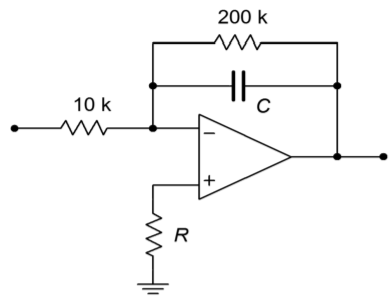
Figure \(\PageIndex{2}\)
6. If \(C = 33\) nF in Figure \(\PageIndex{2}\), determine \(V_{out}\) if \(V_{in}\) is a 200 mV peak sine wave at 50 kHz.
7. Repeat Problem 6 using a 200 mV peak square wave at 50 kHz.
8. Sketch the output of the circuit of Figure 10.2.7 with the input signal given in Figure \(\PageIndex{3}\).
9. Assume that the input to the circuit of Figure 10.2.7 is 100 mV DC. Sketch the output waveform, and determine if it goes to saturation.
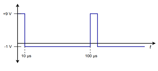
Figure \(\PageIndex{3}\)
10. Sketch the output waveform for Figure 10.2.7, given an input of: \(V_{in}(t) = 0.5 \cos 2 \pi 9000t\).
11. Given the circuit of Figure \(\PageIndex{4}\), sketch the output waveform if the input is a 100 Hz, 1 V peak triangle wave.
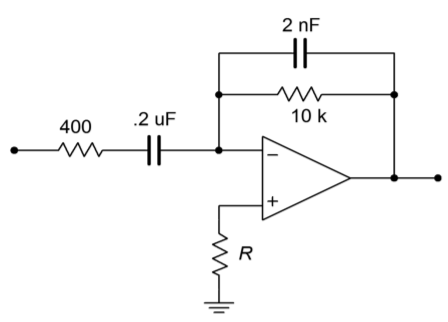
Figure \(\PageIndex{4}\)
12. Repeat Problem 11 if the input is a 2 V peak square wave at 500 Hz. Assume that the rise and fall times are 1 \(\mu\)s and are linear (vs. exponential).
13. Repeat Problem 11 for the following input: \(V_{in}(t) = 3 \cos 2 \pi 60t\).
14. Repeat Problem 11 for the following input: \(V_{in}(t) = 0.5 \sin 2 \pi 1000t\).
15. Repeat Problem 11 for the following input: \(V_{in}(t) = 10 t^2\).
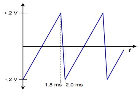
Figure \(\PageIndex{5}\)
16. Given the input shown in Figure \(\PageIndex{5}\), sketch the output of the circuit of Figure 10.19.
17. Given the input shown in Figure \(\PageIndex{5}\), sketch the output of the circuit of Figure 10.19.
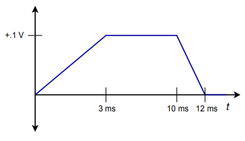
Figure \(\PageIndex{6}\)
18. Sketch the output waveform for Figure 10.3.9, given an input of \(V_{in}(t) = 0.5 \cos 2 \pi 4000t\).
19. Sketch the output waveform for Figure 10.3.9, if \(V_{in}\) is a 300 mV peak triangle wave at 2500 Hz.
Design Problems
20. Given the circuit of Figure \(\PageIndex{1}\),
A) Determine the value of \(C\) required in order to yield an integration constant of −2000.
B) Determine the required of value of \(R\) for minimum integration offset error.
C) Determine \(f_{low}\).
D) Determine the 99% accuracy point.
21. Given the differentiator of Figure \(\PageIndex{7}\), determine the value of \(R\) that will set the differentiation constant to \(−10^3\).
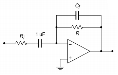
Figure \(\PageIndex{7}\)
22. Determine the value of \(R_i\) such that the maximum gain is 20 for the circuit of Figure \(\PageIndex{7}\). (Use the values of Problem 21.)
23. Determine the value of \(C_f\) in Problem 22 such that noise above 5 kHz is attenuated.
24. Design an integrator to meet the following specifications: integration constant of −4500, \(f_{low}\) no greater than 300 Hz, \(Z_{in}\) at least 6 k\(\Omega\), and DC gain no more than 32 dB.
25. Design a differentiator to meet the following specifications: differentiation constant of \(−1.2E−4\), \(f_{high}\) at least 100 kHz, and a minimum \(Z_{in}\) of 50 \(\Omega\).
Challenge Problems
26. Sketch the output waveform for the circuit of Figure 10.2.7 if the input is the following damped sinusoid: \(V_{in}(t) = 3 \varepsilon −200t \sin 2 \pi 1000t\).
27. A 1.57 V peak, 500 Hz square wave may be written as the following infinite series: \(V_{in} (t)=2 \sum_{n=1}^{\infty} \frac{1}{2 n−1} \sin 2 \pi 500(2n −1)t\)
Using this as the input signal, determine the infinite series output Equation for the circuit of Figure 10.2.7.
28. Sketch the output for the preceding problem. Do this by graphically adding the first few terms of the output.
29. Remembering that the voltage across an inductor is equal to the inductance times the rate of change of current, determine the output Equation for the circuit of Figure \(\PageIndex{8}\).
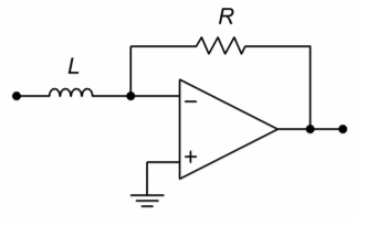
Figure \(\PageIndex{8}\)
30. Repeat the preceding Problem for the circuit of Figure \(\PageIndex{9}\).
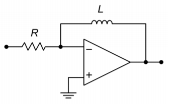
Figure \(\PageIndex{9}\)
31. A 2.47 V peak, 500 Hz triangle wave may be written as the following infinite series: \(V_{in} (t)=2\sum_{n=1}^{\infty} \frac{1}{(2 n−1)^2} \cos 2 \pi 500(2 n −1)t\)
Using this as the input signal, determine the infinite series output Equation for the circuit of Figure 10.3.9.
32. Sketch the output for the preceding problem. Do this by graphically adding the first few terms of the output.
Computer Simulation Problems
33. Simulate Problem 1 and determine the steady-state response.
34. Model Problem 8 using a simulator. Determine both the steady-state and initial outputs.
35. Simulate Problem 14. Determine the steady-state output.
36. Model Problem 22 using a simulator and determine the output signal.
37. Compare the resulting waveform produced by the circuit of Problem 8 using both the 741 op amp and the medium-speed LF411. Does the choice of op amp make a discernible difference in this application?