
10.5: Concerning Practical Inductors
- Page ID
- 52957

Up to this point, inductors have been treated as ideal components, that is, pure inductance. In reality, all inductors have some resistance associated with them due to the resistance of the wire used to make the coil. This is called ESR, or Equivalent Series Resistance. It is also denoted as \(R_{coil}\). Ideally, this resistance will be small enough to ignore, but ultimately it will place a limit on the performance of any circuit that utilizes an inductor.
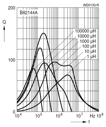
While it is possible to measure the resistance of an inductor using a DMM, this will not yield an accurate value at all frequencies. In fact, as frequency increases, ESR will also increase. This is due to skin effect. At higher frequencies, current is not distributed equally throughout the cross-section of a conductor. In fact, it tends to “hug” the outer surface or “skin” of the conductor. This reduces the effective crosssectional area and thereby increases the resistance1. In general, as frequency rises, so does \(R_{coil}\). Unfortunately, the situation is further complicated by distributed capacitance that will become an issue at still higher frequencies. As a consequence, manufacturers will give a “\(Q\) plot”, such as the one shown in Figure \(\PageIndex{1}\).
The \(Q\), or quality factor, of an inductor can be defined in terms of the peak energy stored in the device versus the energy dissipated per cycle. Keeping time constant, we can relate this to the power via the relation \(i^2R\). The current necessarily is the same for both the reactive and resistive components, therefore the \(Q\) of the coil is equal to the ratio of its reactance to its resistance at the frequency of interest.
\[Q_{coil} = \frac{X_L}{R_{coil}} \label{2.4} \]
Where
\(Q_{coil}\) is the quality factor of the inductor,
\(X_L\) is the magnitude of the inductive reactance at the frequency of interest,
\(R_{coil}\) is the resistance of the inductor at the frequency of interest.
In general, the higher the \(Q_{coil}\), the better. As can be seen in Figure \(\PageIndex{1}\), \(Q_{coil}\) is not a constant. Indeed, it increases with frequency until a peak is reached, at which point it begins to fall.
When dealing with practical inductors, the effective \(Q_{coil}\) can be determined from a graph if the operating frequency is known. Once the \(Q_{coil}\) is found, the effective value of \(Q_{coil}\) can be found from Equation \ref{2.4}. This value can then be placed in series with the ideal inductor to create a more accurate result. For analysis, this pair is sometimes drawn with a box around it to denote that \(Q_{coil}\) is not a separate physical resistor, but is the effective resistance of the inductor.
Example \(\PageIndex{1}\)
Find the voltage across the inductor in the circuit of Figure \(\PageIndex{2}\). Assume the source voltage is \(20\angle 0^{\circ}\) peak-to-peak at a frequency of 20 kHz. \(L\) is equal to 10 mH, \(Q_{coil}\) is 50, and \(R_1\) is \(600 \Omega\).
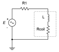
Remember, the inductor consists of both elements within the dashed box. First, find the magnitude of the inductive reactance.
\[| X_L | = 2\pi f L \nonumber \]
\[| X_L | = 2\pi 20 kHz 10 mH \nonumber \]
\[| X_L | = 1257 \Omega \nonumber \]
We can now find \(R_{coil}\) via Equation \ref{2.4}:
\[Q_{coil} = \frac{X_L}{R_{coil}} \nonumber \]
Therefore,
\[R_{coil} = \frac{X_L}{Q_{coil}} \nonumber \]
\[R_{coil} = \frac{1257}{50} \nonumber \]
\[R_{coil} = 25.1 \Omega \nonumber \]
The impedance of the inductor is \(25.1 + j1257 \Omega\), or \(1257\angle 88.9^{\circ} \Omega\). The total impedance is \(600 + 25.1 + j1257 \Omega\), or \(1404\angle 63.6^{\circ} \Omega\). We can use a voltage divider to find the inductor's voltage.
\[v_{ind} = e \frac{Z_{ind}}{Z_{Total}} \nonumber \]
\[v_{ind} = 20 \angle 0^{\circ} Vpp \frac{1257\angle 88.9^{\circ} \Omega}{1404 \angle 63.6^{\circ} \Omega} \nonumber \]
\[ v_{ind} = 17.9\angle 25.3^{\circ} Vpp \nonumber \]
It is worth noting that, due to the coil resistance, the inductor's current and voltage are not precisely 90\(^{\circ}\) out of phase, but rather 88.9\(^{\circ}\). That's a small but measurable deviation.
References
1Recall that \(R = \rho l / A\). A decrease in area \(A\) results in increased resistance, \(R\).