
5.3.1: The Kaplan and Francis Turbines
- Page ID
- 84786
The kinetic energy of the “water jet” is harnessed and converted to mechanical work (needed for turning the electricity generator). A widely used turbine type is the Kaplan Turbine, looking very much like a giant propeller. Its efficiency is very high, it can “capture” over 90% of the kinetic energy of the outlet stream. Today, however, another turbine type is taking over – namely, the Francis Turbine (Fig. 5.11). It was invented 170 years ago by a Massachusetts engineer James B. Francis. Mechanically, it’s design is more
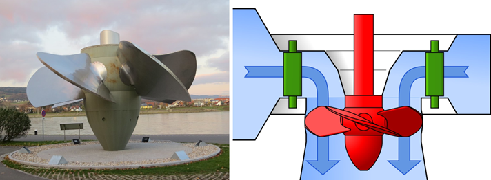
complicated than that of the Kaplan turbine. Also, its efficiency is slightly lower than the Kaplan’s turbine efficiency. Yet, it has one considerable advantage over the Kaplan type – name, it is a reversible machine,
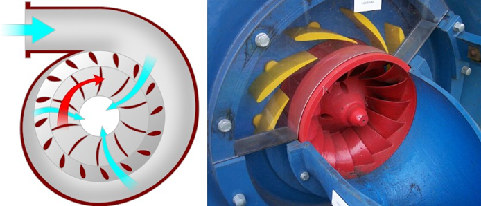
Figure 5.10: The flow of water in the Francis turbine (left diagram – see the text for more explanation) and, in the right, a photograph of a real turbine with partially exposed elements, the yellow vanes and the red runner (source: Wikimedia Commonas).
it can work in two directions: (i) as a turbine harnessing the energy from down-flowing water, and (ii) as an electric motor-powered pump, capable of lifting water from one reservoir to another one, located much higher (even 2000 ft. higher). Such capability makes the Francis turbines especially valuable in Pumped Storage Hydroelectic Plants (PSHP) which are becoming more and more popular – we will return to the discussion about the advantages of pumped-storage plants later in this Chapter.
While the operation of the Kaplan turbine seems quite simple and does not require any special explanation (everybody on many occasions have had some experience with propellers – those in toys, in motor boats, in portabe fans, etc., right?) – the operating principle of the Francis turbine may not be immediately clear, if we look only at photographs and diagrams.So it’s a good idea to explain the role of individual components in the device. A pretty good description if given in a Wikipedia article – here is, in short, how it explains the things: as shown in the diagram on the left in Fig. 5.10, water enters a spiral casing (known as the “volute casig”, or the “scroll case”), inside which there is a rotor, usually called a “runner”. Throughout the casing’s length there are numerous openings (known as wicket gates or simply “wickets”) through which water flows inwards and impinge on the blades of the rototr. As can bee seen in the scheme in Fig. 5.10, the cross section area of the spiral casing gradually decreases along its circumference in order to maintain constant speed of water along the casing despite the fact that its volume gradually decreases. In addition, in each wicket gate there is a “stay vane”, i.e., a profiled blade (the yellow blades in the right photograph in Fig. 5.10) that allows to send the water streams impinging on the rotor at different angles, appropriately to the speed at which it rotates.
However, an even better way of explaining the Francis’ turbine operatio n principle is definitely to use a dynamic video presentation – for instance, one such YouTube piece worth recommending is this one.
In addition to the “reversibility”, another important advantage of the Francis turbines is that they allow to maintain the a constant speed of rotation even when the flow of the input water varies in a wide range. Today, almost all turbines installed in new hydropower plants are of the Francis type, and about 60% of the hydropower generated worldwide comes from such turbines.
It is also worth looking at the animated picture in this website which shows the “block scheme” and the operation of a typical hydropower plant (note that the tube through which water from the reservoir reaches the turbnbe is called “the penstock”). There are also several similar movie clips in YouTube, e.g., this nice short video from New Zealand. In some of the static or animated pictures in the Web (not in the two linked above!).
One thing is shown incorrectly –namely, the penstock’s inlet is positioned close to the reservoir bottom. In fact, it’s typically located close to the water surface. But no matter from where the water is taken, the kinetic energy of the flow reaching the turbine is the same – can you explain why?