
8.4: Ocean Thermal Energy Conversion (OTEC)
- Page ID
- 85141
All the methods of extracting energy from oceans and seas we have so far discussed in this Chapter have one thing in common: they are all based on harnessing energy from different forms of water motion. More accurately, they convert kinetic and potential energy of flowing waters to electric energy. In OTEC, however, the kinetic and potential energy of water is irrelevant – it’s the thermal energy that is converted to electricity.
OTEC is in certain respect similar to electricity generation from low temperature geothermal waters, described in the Geothermal Energy Chapter. Both method use a heat engine. A heat engine, let's recall, needs a "hot source" of higher temperature \(T_{\text {hot }}\), and a "cold source" of lower temperature \(T_{\text {cold }}\) (let's always remember, these temperatures should be given in absolute scale, i.e., in Kelvins). In geothermal facilities, the "hot source" is water pumped from a deep well reaching a geothermal reservoir. And the most often used "cold source" is surface water, e.g., from a stream or a lake.
In an OTEC installation, in contrast, the scheme is "reversed": the "cold source" is ocean water pumped from a depth of 1000 meters, and the "hot source" is surface water. One interesting property of all oceans is that at a \(1000 \mathrm{~m}\) depth the water temperature is always close to \(4-5{ }^{\circ} \mathrm{C}\), i.e. to \(T=277278 \mathrm{~K}\). No matter whether it's close to the Equator, or close to the North Pole. And the "hot source" is the water at the ocean's surface.
Let's now recall that the highest theoretical efficiency of a thermal engine is given by the Carnot Law:
\[\epsilon=1-\frac{T_{\text {cold }}}{T_{\mathrm{hot}}} \]
and the maximum efficiency of a power-maximizing thermal engine is:
\[ \epsilon^{\prime}=1-\sqrt{\frac{T_{\text {cold }}}{T_{\mathrm{hot}}}} \]
So, for obtaining a good conversion efficiency \(T_{\text {hot }}\) should be considerably the difference will be to high. But at tropical lattitudes, the temperature of the surface waters may be \(25^{\circ} \mathrm{C}=298 \mathrm{~K}\) or even higher. One can therefore obtain a realistic efficiency \(\varepsilon^{\prime}=1 \quad-(278 / 298)^{1 / 2}=0.034=3.4 \%\). Well? Not particularly impressive?... In conventional coal or natural gas burning thermal power plants the efficiency may be event ten times higher... But let's keep in mind that coal and natural gas cost money, and here the thermal energy used is for free!1 So, it may be worth going for it. And this is exactly the idea of an OTEC power plant.
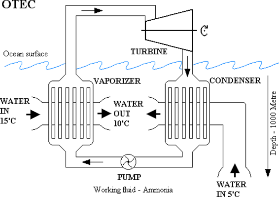
In all practical implementations of OTEC installations, the thermal engines used are steam turbines. Of course, one should use not water as the working fluid, but something with the boiling temperature much lower than \(T_{\text {hot. }}\) As in the case of low-temperature geothermal power plants, a good choice may be ammonia \(\mathrm{NH}_{3}\), circulating in a closed system. The basic scheme of such a system is shown in Fig. 8.18. Liquid ammonia is pumped through an "evaporator" - i.e., a heat exchanger, through which also "hot" surface water is run. The heat from water is passed to ammonia, which boils and changes to gas, or "ammonia steam". It's then passed to the turbine, where its thermal energy is converted to mechanical work. In the process, the ammonia gas cols down, but it's still a gas. So, it has to be converted back to a liquid, which requires taking away another portion of heat from it. It's therefore sent to another heat exchanger, called "condesor", through which cold water pumped from the depth is passing. The ammonia gas gives away its remaining heat to the cold water and condensates back to a liquid. Finally, it passes through a pump, which injects it back to the evaporator.
As noted, there are some cost involved. Some power is needed to pump surface water through the evaporator. Some more power is needed to run the pump (labeled as 4 in Fig. 8.18). And much more power is needed for pumping cold water from the \(1000 \mathrm{~m}\) dept and through the condenser. In practice, all that power needed consumes about \(50 \%\) of the electric power generated.
In 1974, The U.S. established the Natural Energy Laboratory of Hawaii Authority (NELHA) at Keahole Point on the Kona coast of Hawaii. Hawaii is an ideal site for OTEC research: the temperature of surface waters is high, 25◦ or more. From the coasts, there is a relatively easy access to deep cold waters: the Hawaiian Islands are essentially steep-slope mountains, rising from the bottom of the Pacific, more than 3 miles deep at that area. So, access to cold water can be obtained by lowering a pipeline along the steep underwater slope.
In 1993 a 255 kW4 prototype OTEC power plant started operating at the Keahole Point, and continued running for six years. The experience gained over that period was used to design a new permanent OTEC installation. And, indeed, on August 25, 2013 a new 105 kW installation started operating, when the Hawaii Governor, David Ige, symbolically ”flipped the switch” to activate it. The power is not particularly impressive, but, in contrast to the installation tested in the 1990-s, the new one is connected to the grid. And it’s still not the end of the long-range project, which is a part of the plan of making Hawaii totally energy-independent by 2045. The next OTEC-related step in the plan is to build a 10-20 MW size installation.

)
The OTEC technique isn’t not a new idea. It was first proposed almost 140 years ago by a French physicist Jacques-Arsene d’Arsonval. His student, Georges Claude, built the first-ever working 22 kW OTEC installation at Cuba in 1930. More about the OTEC history and the status of this tech- nology can be found in a Wikipedia article, or in this Way2Science Web page.
OTEC can be used only where the surface water temperature is high enough. But there are many such places. The installations should not neces- sarily be located at the coasts. Other possible locations are off-shore platform on continental shelves, or floating OTEC power plants. The latter may be located at places where the oceans is 1000 m deep and then use a vertical
cold-water pipeline, which is the easiest to install. Different assessments re- ported estimate the available global OTEC resources (i.e., as much power can be extracted, without disrupting the thermal equilibrium of oceans) to be from 30% to as much as 2-3 times the current global consumption of electric power.
The latter figures would mean that we would be able to supply the en- tire world with OTEC electricity, and still much extra capacity would be available, if needed. A considerable advantage of OTEC power is that – like geothermal power – it is available at a constant level for 24 hours per 7 days in a week. Well, it is available only in geographical areas lying not so far from the Equator ( 10◦ 15◦). But this is not an unsolvable problem, electric power can be sent over distances of thousands of miles! So, why don’t we rush to shut down all the dirty coal burning power plants and start building large OTEC facilities? Well, for sure the major culprit for the lack of action is the prohibitively high initial cost. It’s sad. But at least one thing is optimistic: if one day we run out of fossil fuels, then even OTEC alone may be able to supply us with no less electric power than we obtain now by burning those dirty CO2 emitters. And add tide power, geothermal power, all other renewable sources – there is absolutely no fear that there would be a catastrophic never-ending power outage when all the fossil fuels resources are completely emptied. But what about the prohibitively high costs of replacing the fossil fuel plants with renewable power sources? Don’t worry! When brown-outs and black-outs become more often and last longer and longer, the governments will gladly revise the budgets and find money to deal with those “prohibitively high costs”.
An example: at the end, let’s work on an example which will make it easier perhaps to understand why the costs are “prohibitively high”. Consider an OTEC installation in which the 25◦C (298 K) surface water is used. The thermal engine in the installation extracts the heat from it, and in the process it’s cooled down to 15◦C (288 K) in the “evaporator”, and is returned to the ocean as “wastewater” (as shown in Fig. \(\PageIndex{1}\)).
Suppose that one ton (1000 kg) of the surface water runs through the evaporator. Specific heat of seawater (the amount of heat that has to be added to a mass unit to heat it up by 1 K, or taken away from a mass unit to cool it down by 1 K) is 3.85 kJ/kg K. OK, so if 1000 kg of seawater is passed through the evaporator and cooled by 10K, the amount of heat taken away from it is:
\[ \Delta Q=1000 \mathrm{~kg} \times 10 \mathrm{~K} \times 3.85 \mathrm{~kJ} / \mathrm{kg} \cdot \mathrm{K}=38500 \mathrm{~kJ}=38.5 \mathrm{MJ} \]
Now, suppose that the thermal efficiency of the heat engine used in the installation is \(E^{\prime}=3.4 \%=0.034\), as we obtained earlier from the Eq. 8.5. It means that \(3.4 \%\) of \(\Delta Q\) is converted to work \(W\) :
\[ w=\Delta Q \times \epsilon^{\prime}=38.5 \mathrm{MJ} \times 0.034=1.309 \mathrm{MJ} . \]
Suppose that the installation "consumes" \(1000 \mathrm{~kg}\) of surface water every second. So, it delivers 1.309 MJ of power every second, i.e., 1.309 MW of power.
OK, it follows from the above that to get \(1 \mathrm{MW}\) of output power from the turbine, we need to use \(1000 \mathrm{~kg} / 1.309=764 \mathrm{~kg}\) of water every second. Since the density of ocean water is \(1025 \mathrm{~kg} / \mathrm{m}^{3}\), the volume of \(764 \mathrm{~kg}\) of water is \(0.775\) cubic meter. OK, it still doesn't look scary, does it?
But \(1 \mathrm{MW}\) is not so much of power. The average consumption of electric power is about \(6 \mathrm{GW}\). So, if we wanted to build an OTEC of \(1 \mathrm{GW}\) power, we have to multiply \(0.775 \mathrm{~m}^{3}\) by one thousand, which is 775 cubic meters per second. Is it much or isn't it? Well, do you know what's the discharge of our Willamette River at it mouth? The long time average, the Web says, is 933 \(\mathrm{m}^{3} / \mathrm{s}\). So, for \(1 \mathrm{GW}\) output power one would to run through the evaporator a stream of water equal to about \(80 \%\) of the water discharge of Willamette. And for \(6 \mathrm{GW}\), it would be \(4650 \mathrm{~m}^{3} / \mathrm{s}\). The discharge of Columbia River is \(7,500 \mathrm{~m}^{3} / \mathrm{s}\). So, to get our \(6 \mathrm{GW}\), we would need to run through the evaporator a "river" of water as big as \(62 \%\) of the Columbia River!
I think the above is a good illustration of the scale of the challenges that future builders of large-scale OTEC power plants would face...
____________________________________________________
1. Not exactly... One has to pay, too, but not with money. In a moment, it will be explained.
2. 250 kW was the output power of the generator. But the net power generated was only about one-half of it, after correcting for the power needed to run all pumps.