
11.4.3: Electricity → Kinetic Energy → Electricity Storage Scheme
- Page ID
- 84616
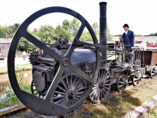
Another form of mechanical energy that can be stored is that associated with the body motion – i.e., the kinetic energy. For obvious reasons, rectilinear motion cannot be taken into account – but rotary motion is well suited for this purpose. Heavy spinning wheels began to be used as a kind of “energy buffers” over 200 years ago and the term “flywheel” was already created. Well, what flywheels were used for was not yet energy storage in the exact sense in which we understand it today. Their role was initially to “smooth” the motion of steam engines, which without it exhibited unpleasant jerks.
For the first time, the flywheel was used as a “reusable battery” i.e. a system that could be charged with energy, keep it stored for some time and finally return it in Switzerland around 1950 in the so-called “gyrobuses”. A 1500 kg flywheel was installed in the bus. An electric motor accelerated the wheel to 3000 revolutions per minute. Then the same motor acted as a generator and the current from it propelled the vehicle. From a single “charge” the gyrobus could make about 4 miles. But at each stop along the bus’ route , the wheel was recharged for a minute or two, so that the vehicle could operate a line even as long as 20 miles. The gyrobuses offered a nice low-noise and zero-emission means of urban public transportation, but the world in the 1950s was flooded with cheap oil, so they eventually succumbed to the competition with diesel buses.
The kinetic energy stored in a spinning flywheel is:
\[ K=\dfrac{4\pi^{2}f^{2}I}{2} \notag\]
where I is the wheel’s moment of inertia, and f is the number of revolutions per second. Most often, however, the speed of rotation is given not in revolutions per second, but in revolutions per minute (RPM). If a wheel spins too fast, it may be torn apart by centrifugal forces. The maximum speed at which a given wheel can spin depends on its radius, shape and the strength of material from which it is made. The energy density i.e., the maximum energy that can be stored per unit weight for steel flywheels is higher than for lead batteries. And when using materials with extremely high tensile strength (such as, e.g., carbon fiber composites), the energy density of such flywheels may reach some 50% of that of the best lithium-ion cells manufactured today (written in April 2020). However, there are problems that hinder the widespread use of such energy storage. Until recently, only mechanical bearings were available, which always lose energy due to friction. Even when using the highest quality bearings, the “self-discharging” rate of such flywheels could amount to as much as 20-50% energy loss per hour.
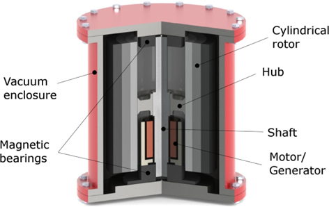
The technology of making “flywheel batteries” capable of storing energy for many hours or even days have only recently emerged, thanks to the invention of zero-friction bearings based on the phenomenon of magnetic levitation. As is well known, magnets facing each other with identical poles experience a repulsive force. The repulsion can be strong enough to overcome the force of gravity and one magnet can float above the other without touching it. So, there is essentially no friction, with the exception of that caused by surrounding air (which can be eliminated by putting the spinning object in evacuated space).
A very good demonstration of the phenomenon of magnetic levitation is the educational toy known as the “levitating spinning top”. There are a number of short videos on YouTube, here we provide links to such (one from the US, the other from China) in which hobbyists make such spinning tops. Magnetic levitation can lift not only spinning tops, but also bricks and even flywheels with a mass of hundreds of kilograms. The latter generally are enclosed in an evacuated container in order to eliminate air friction.
Magnetic levitation bearings poorly absorb shocks and changes in the orientation of the spin axis. Therefore, flywheels with such bearings are not suitable for use in vehicles, but they can perform very well in stationary systems. Another limitation for bearings is weight certain limits cannot be exceeded. Therefore, flywheel manufacturers concentrate on the production of modular systems that can be scaled up that is, a number of individual modules can be combined and form one large assembly.
For example, the Californian company Amber Kinetics produces M-32 modules, each of which can store 32 kWh of energy and provide an output of 8 kW. According to the M-32 data sheet, the “self-discharge” power loss of such a module is less than 100 W, i.e. after 24 hours the energy loss will be less than 2.4 kWh, or below 7.5 % of the initially stored energy. 125 M-32 modules will form a group with an output of 1 MW.
The German company STORNETIC produces modules called Enwheel 22, capable of storing 3.6 kWh and providing an output of 22 kW. These modules can be grouped in standard shipping containers. 28 modules packed into a standard 40-foot container deliver 616 kW of output power.
As follows from the above, flywheel based systems are unlikely to be suitable for long-term energy storage. But this is not their main task an important role they play is stabilization of the power grid specifically, frequency stabilization. If the grid in certain area is operating at the limit of its performance and the load suddenly increases even more, then the generators in power plants stop keeping up, their rotational speed drops and so does the frequency of the alternating current they generate. This is a very dangerous phenomenon that can lead to a collapse of the entire power grid in a smaller or larger area. The remedy is a sudden injection of additional power flywheel based systems are great for this, they can react in a split second. The boost of extra power they deliver can prevent a dangerous situation.
However, there is a special category of vehicles in which flywheels are well suited for energy storage namely, space ships. NASA is absolutely serious about this and it has created a prototype that can be viewed in this YouTube video.