
3.4.1: Introduction to MOSFETs
- Page ID
- 89968

We now move on to a three-terminal device the transistor. (In truth, this device really has at least four, and probably five, terminals, but we will leave the subtle details for a later time.) We will now focus on a device called the Field Effect Transistor, or Metal-Oxide-Semiconductor Field Effect Transistor, or simply the MOSFET. The vast majority of transistors in use or MOSFETS, if you are reading this on a device, you are probably relying on several billion MOSFETS. Consider the following:
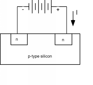
Here we have a block of silicon, doped p-type. Within it we have made two regions which are doped n-type. To each of those n-type regions we attach a wire, and connect a battery between them. If we try to get some current \(I\) to flow through this structure, nothing will happen, because the n-p junction on the right hand side is reverse biased (We have the positive lead from the battery going to the n-side of the p-n junction). If we attempt to remedy this by turning the battery around, we will now have the LHS junction reverse biased, and again, no current will flow. If, for whatever reason, we want current to flow, we will need to come up with some way of forming a layer of n-type material between one n-region and the other. This will then connect them together, and we can run current in one terminal and out the other.
To see how we will do this, let's do two things. First we will grow a layer of \(\mathrm{SiO}_{2}\) (silicon dioxide, or just plain "oxide") on top of the silicon. (This turns out to be relatively easy: we just stick the wafer in an oven with some oxygen flowing through it, and heat everything up to about \(1100 ^{\circ} \mathrm{C}\) for an hour or so, and we end up with a nice, high-quality insulating \(\mathrm{SiO}_{2}\) layer on top of the silicon). On top of the oxide layer we then deposit a conductor, which we call the gate. In the "old days" the gate would have been a layer of aluminum (Hence the "metal-oxide-silicon" or MOS name). Today, it is much more likely that a heavily doped layer of polycrystalline silicon (polysilicon, or more often just "poly") would be deposited to form the gate structure. (I guess "POS" sounded funny to people in the field, because it never caught on as a name for these devices). Polysilicon is made from the reduction of a gas, such as silane \(\left(\mathrm{SiH}_{4}\right)\) through the reaction
\[\ce{SiH4 \ g -> Si + 2H2(g)} \nonumber\]
The silicon is polycrystalline (composed of lots of small silicon crystallites) because it is deposited on top of the oxide, which is amorphous, and so it does not provide a single crystal "matrix" which would allow the silicon to organize itself into one single crystal. If we had deposited the silicon on top of a single crystal silicon wafer, we would have formed a single crystal layer of silicon called an epitaxial layer. (Epitaxy comes from the Greek, and it just means "ordered upon". Thus an epitaxial layer is one which follows the order of the substrate on which it is grown). This is sometimes done to make structures for particular applications. For instance, growing a n-type epitaxial layer on top of a p-type substrate permits the fabrication of a very abrupt p-n junction.