
6.1.4: Plasma Displays
- Page ID
- 88160
Plasma displays most notably use the properties of plasma as a light source. Plasma is created by energizing a gas, increasing the number of electrons within the gas. This creates an imbalance of charges and effectively ionizes the gas, putting it in the state of plasma. Plasma is highly conductive in the presence of an electromagnetic field.
How Plasma Display Panels Work
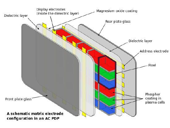
The structure of PDPs consist of multiple layers of various materials, as seen in figure. The inner most layer consists of a series of 3 cell compartments which make up a single pixel of the projected image. Each cell contains a gas mixture of noble gases, usually neon with 10-15% xenon, and is responsible for producing one of the three primary colors, red, blue, or green. Outside of these cells is the layer of dielectric material and electrodes that provides energy to each of the 3-cell chambers. The dielectric layer allows for more charge to gather between the electrodes and the cells. On the projection side of the display, the electrodes are vertical and transparent. These electrodes are known as the transparent display electrodes and are coated in magnesium oxide, while the back electrodes are known the address electrodes. The outer most part of the plasma display are the glass layers, one of which the image is shown on.
The way plasma displays work is similar to how a florescent light bulb works, gas is used to excited phosphors which produce visible light. In plasma displays a voltage is given to the gas within the cells and the gas becomes ionized, creating plasma. The plasma itself does not provide the light energy itself, rather it produces ultraviolet, UV, light that excites the phosphors that are coated on to each cell. The color that is produced (either red, green, or blue) is dependent on the phosphor. Red light is produced by phosphors such as (Y,Gd)BO3:Eu, YBO3:Eu, and Y2O3:Eu. Blue light is produced by phosphor such as (Y,Gd)(V,P)O4 and BaMgAl14O23:Eu. Green light is produced with phosphor such as Zn2SiO4:Mn, BaAl12O19:Mn, and SrAl12O19:Mn. By varying the intensity of the red, green, and blue cells, all colors in the spectrum can be achieved.
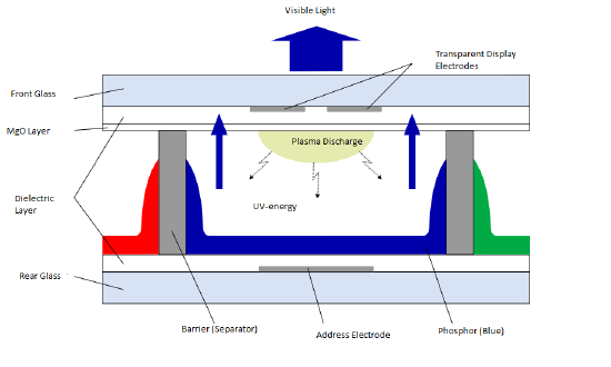
In order to start this process, a control box within the display gives power to both electrodes at the specific intersection that a pixel is needed to be illuminated. The electrode then provides a voltage that adds electrons to the gas mixture. The addition of electrons causes collisions between the added electrons and the neutral atoms of the gas. These atoms lose some of their electrons which causes them to ionize and have a net charge, creating plasma. As current from the electrodes goes through the cells, the now positive ions and electrons move to the respective side of the current, positive ions move to the negative side and electrons move to the positive side. During this movement more collisions occur between the electrons and ions. This creates energy and causes the electrons that are in the ion to get to an excited state briefly. When these electrons come down to the lower orbital of less energy, they release the excess energy in the form of an UV photon. The energy from the UV photons cause the phosphors in the cell to be excited and emit light in the visible spectrum, a seen in figure 2. The combination of numerous cells emitting varying degrees of light and color creates the digital image that occurs, and the constant turning off and on of electrodes allows for these images to move.
Properties of PDPs
Plasma displays show many advantages in comparison to other types of displays. Since each cell contains a light source, in the form of plasma, each pixel is light controlled. This allows PDPs to have a typical brighter display than CRT and LCD screens. In addition to this PDPs have a higher refresh rate which result in faster reaction time and less motion blur. Compared to CRT screens, PDPs are much thinner and lighter weight but roughly consume the same amount of power.
One of the draw backs to plasma displays is the effect of image burn-in. Image burn-in occurs when an image is held on a plasma display for too long a shadow of the image is burnt in to the screen. When a stationary image is set for long periods, the phosphors will overheat and lose their luminosity. Although the shadow image does not always occur, over time the decline in luminosity cause the overall image quality to decline as well. A similar effect occurs when cells display bright color for long periods of time. The cells experience a large build up of charge and the result is also a shadow image, however this is resolved by powering off the screen and allowing the cells to discharge.
History of Plasma Displays
 In July of 1964, the first prototype of a plasma display monitor was invented by Professor Gene Slottow and Professor Donald Blitzer at the University of Illinois. This prototype (figure 3) had a monochrome display of neon orange, but was not commercially viable. In 1983, IBM released another neon orange monochrome plasma display that was 48 cm in length. The first full color plasma display came out in 1992 from Fujitsu, which measured at 53 cm and was notably brighter than other displays. In 1997 Fujitsu commercially released a 107 cm plasma display with a resolution of 852x480 pixels. These displays were, while commercially available, were mostly expensive at roughly $14,999. More recently, LCD have grown in popularity and the high price of plasma displays,in addition to the LCDs superior features such as lower power consumption and lighter weight, have caused a downfall in popularity.
PLATO computers.
Questions:
1. Which phosphors produce red light?
2. How is an image in a plasma display produced?
3. What is screen burn-in?
Answers:
1. (Y,Gd)BO3:Eu, YBO3:Eu, and Y2O3:Eu can all be used to produce red light.
2. Electrodes excite gases in the cell of the display, which creates plasma. Plasma releases UV-light waves that react with phosphor coating producing colored light. Millions of these cells, each forming a pixel of the image, work simultaneously to project a digital image.
3. When a stationary image is left on the screen of a plasma display, the phosphors overheat and leave a mark of the image on the screen.
Additional Links
Plasma (ChemWIki)
Dielectrics (ChemWIki)
Visible Light (ChemWIki)
References:
Contributors and Attributions
Don Lee Valles (University of California, Davis)