
4.3.1: Constant Density in Gravitational Field
- Page ID
- 661

The simplest case is when the density, \(ρ\), pressure, \(P\), and temperature, \(T\) (in a way no function of the location) are constant. Traditionally, the \(z\) coordinate is used as the (negative) direction of the gravity. The effective body force is
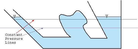
Fig. 4.2 Pressure lines in a static fluid with a constant density.
Utilizing equation (9) and substituting it into equation (8) results into three simple partial differential equations. These equations are
\[
\dfrac {\partial P}{\partial x} =
\dfrac {\partial P}{\partial y} = 0
\label{static:eq:dxy}
\]
and
Pressure Change
\[
\label{static:eq:dz}
\dfrac{\partial P}{\partial z} = -\rho\, \mathbf{g}
\]
Equations (10) can be integrated to yield
\[
P(x,y) = constant
\label{static:eq:dxyS}
\]
and constant in equation (12) can be absorbed by the integration of equation (11) and therefore
\[
P(x,y,z) = -\rho\, g\, z + constant
\label{static:eq:dzS}
\]
The integration constant is determined from the initial conditions or another point. For example, if at point \(z_0\) the pressure is \(P_0\) then the equation (13) becomes
\[
P(z) -P_0 = -\rho \, g\, ( z - z_0)
\label{static:eq:dzSExplisit}
\]
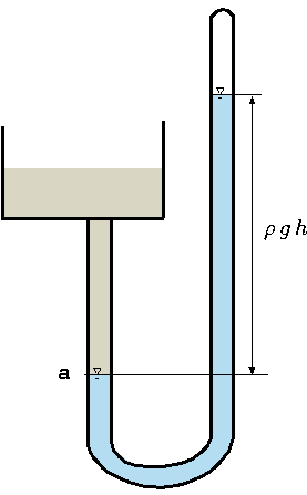
Fig. 4.3 A schematic to explain the measure of the atmospheric pressure.
It is evident from equation (13) that the pressure depends only on \(z\) and/or the constant pressure lines are in the plane of \(x\) and \(y\). Figure 4.2 describes the constant pressure lines in the container under the gravity body force. The pressure lines are continuous even in area where there is a discontinuous fluid. The reason that a solid boundary doesn't break the continuity of the pressure lines is because there is always a path to some of the planes. It is convenient to reverse the direction of \(z\) to get rid of the negative sign and to define \(h\) as the dependent of the fluid that is \(h quiv − ( z − z_0 )\) so equation (14) becomes
Pressure relationship
\[
\label{static:eq:hStatic}
P(h) - P_0 = \rho\, g\, h
\]
In the literature, the right hand side of the equation (15) is defined as piezometric pressure.
Example 4.1
Two chambers tank depicted in Figure 4.4 are in equilibration. If the air mass at
\hbox to \textwidth {chamber A is 1 Kg while the mass at chamber B is unknown. The difference in the}
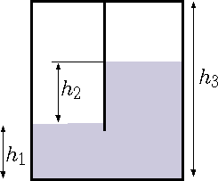
Fig. 4.4 The effective gravity is for accelerated cart.
liquid heights between the two chambers is \(2[m]\). The liquid in the two chambers is water. The area of each chamber is \(1[m^2]\). Calculate the air mass in chamber B. You can assume ideal gas for the air and the water is incompressible substance with density of \(1000[kg/m^2]\). The total height of the tank is \(4[m]\).
Assume that the chamber are at the same temperature of \(27^{\circ}C\).
Solution 4.1
The equation of state for the chamber A is
\[
\label{twoChambers:gasA}
m_A = \dfrac{R\,T}{P_A\,V_A}
\]
The equation of state for the second chamber is
\[
\label{twoChambers:gasB}
m_B = \dfrac{R\,T}{P_B\,V_B}
\]
The water volume is
\[
\label{twoChambers:totalV}
V_{total} = h_1\, A + (h_1+h_2)A = (2\,h_1+ h_2)\, A
\]
The pressure difference between the liquid interface is estimated negligible the air density as
\[
\label{twoChambers:DeltaP}
P_A - P_B = \Delta P = h_2 \, \rho\,g
\]
combining equations (16), (17) results in
\[
\label{twoChambers:EeltaPe}
\dfrac{R\,T}{m_A\,V_A} - \dfrac{R\,T}{m_B\,V_B} = h_2 \, \rho\,g
\Longrightarrow
\left( 1 - \dfrac{1}{\dfrac{m_B}{m_A} \,\dfrac{V_B}{V_A}} \right) =
\dfrac{h_2 \, \rho\,g\,m_A\,V_A}{R\,T}
\]
In equation the only unknown is the ratio of \(m_B/m_A\) since everything else is known. Denoting \(X= m_B/m_A \) results in
\[
\label{twoChambers:almostSol}
\dfrac{1}{X} = 1 - \dfrac{h_2 \, \rho\,g\,m_A\,V_A}{R\,T} \Longrightarrow
X = \dfrac{1} {1 - \dfrac{h_2 \, \rho\,g\,m_A\,V_A}{R\,T} }
\]
The following question is a very nice qualitative question of understanding this concept.
Example 4.2
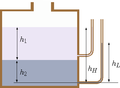
Fig. 4.5 Tank and the effects different liquids.
A tank with opening at the top to the atmosphere contains two immiscible liquids one heavy and one light as depicted in Figure 4.5 (the light liquid is on the top of the heavy liquid). Which piezometric tube will be higher? why? and how much higher? What is the pressure at the bottom of the tank?
Solution 4.2
The common instinct is to find that the lower tube will contain the higher liquids. For the case, the lighter liquid is on the top the heavier liquid the
the top tube is the same as the surface. However, the lower tube will raise only to (notice that \(g\) is canceled)
\[
\label{whoIsHigh:second}
h_L = \dfrac{\rho_1\,h_1 + \rho_2\,h_2}{\rho_2}
\]
Since \(\rho_1 > \rho_1\) the mathematics dictate that the height of the second is lower. The difference is
\[
\label{whoIsHigh:ratio}
\dfrac{h_H - h_L}{h_2} = \dfrac{h_H}{h_2} - \left( \dfrac{\rho_1\,h_1 + \rho_2\,h_2}{h_r21\,\rho_2} \right)
\]
It can be noticed that \(h_H=h_1+h-2\) hence,
\[
\label{whoIsHigh:ratioC}
\dfrac{h_H - h_L}{h_2} = \dfrac{h_1+h_2}{h_2} - \left( \dfrac{\rho_1\,h_1 + \rho_2\,h_2}{h_2\,\rho_2} \right)
= \dfrac{h_1}{h_2} \left(1 - \dfrac{\rho_1}{\rho_2} \right)
\]
or
\[
\label{whoIsHigh:ratioF}
h_H - h_L = {h_1}\, \left(1 - \dfrac{\rho_1}{\rho_2} \right)
\]
The only way the \(h_L\) to be higher of \(h_H\) is if the heavy liquid is on the top if the stability allow it. The pressure at the bottom is
\[
\label{whoIsHigh:pressure}
P = P_{atmos} + g\,\left( \rho_1\,h_1 + \rho_2\,h_2 \right)
\]
Example 4.3
The effect of the water in the car tank is more than the possibility that water freeze in fuel lines. The water also can change measurement of fuel gage. The way the interpretation of an automobile fuel gage is proportional to the pressure at the bottom of the fuel tank. Part of the tank height is filled with the water at the bottom (due to the larger density). Calculate the error for a give ratio between the fuel density to the water.
Solution 4.3
The ratio of the fuel density to water density is \(arsigma= \rho_f/\rho_w\) and the ratio of the total height to the water height is \(x= h_w/h_{total}\) Thus the pressure at the bottom when the tank is full with only fuel
\[
\label{waterCar:fullP}
P_{full} = \rho_f\,h_{total}\,g
\]
But when water is present the pressure will be the same at
\[
\label{waterCar:waterP}
P_{full} = \left(\rho_w \,x\,+ \phi\,\rho_f\right) g\,h_{total}
\]
and if the two are equal at
\[
\label{waterCar:Pequal}
\rho_f\,\cancel{h_{total}}\,\cancel{g} = \left(\rho_w \,x\,+ \phi\,\rho_f\right) \cancel{g}\,
\cancel {h_{total}}
\]
where \(\phi\) in this case the ratio of the full height (on the fake) to the total height. Hence,
\[
\label{waterCar:sol}
\phi = \dfrac{\rho_f - x\,\rho_w}{\rho_f}
\]
Contributors and Attributions
Dr. Genick Bar-Meir. Permission is granted to copy, distribute and/or modify this document under the terms of the GNU Free Documentation License, Version 1.2 or later or Potto license.