4.10: Numerical Experiment (Circuit Design)
- Page ID
- 10118
Our analysis in Example 1 from "Linear Algebra: Circuit Analysis" and Problem 1 from "Linear Algebra: Circuit Analysis" indicates that not enough current will flow through the lamp to make it glow. We now wish to change the resistance of the 100 ohm resistor to a new value so that the lamp will glow. We replace 100 in the equations with an unknown resistance \(R\). Equation 2 is unchanged, but Equation 6 becomes
\[\begin{align}
& \tfrac{\left(v_{2}-v_{1}\right)}{50}+\tfrac{v_{2}}{300}+\tfrac{\left(v_{2}-v_{3}\right)}{R}=0 \nonumber \\
\Rightarrow & 6 R\left(v_{2}-v_{1}\right)+R v_{2}+300\left(v_{2}-v_{3}\right)=0 \nonumber \\
\Rightarrow &-6 R v_{1}+(7 R+300) v_{2}-300 v_{3}=0 \label{}.
\end{align} \nonumber \]
Equation 7 from "Linear Algebra: Circuit Analysis" becomes
\[\begin{align}
\tfrac{\left(v_{3}-v_{2}\right)}{R}+\tfrac{v_{3}}{2}=0 \nonumber \\
\Rightarrow \quad 2\left(v_{3}-v_{2}\right)+R v_{3}=0 \nonumber \\
\Rightarrow \quad 0 v_{1}-2 v_{2}+(R+2) v_{3}=0 \label{}
\end{align} \nonumber \]
The matrix form of these equations is
\[\left[\begin{array}{lll}
1 & & 0 & 0 \\
-6 R & 7 R & +300 & -300 \\
0 & & -2 & R+2
\end{array}\right]\left[\begin{array}{l}
v_{1} \\
v_{2} \\
v_{3}
\end{array}\right]=\left[\begin{array}{l}
5 \\
0 \\
0
\end{array}\right] \nonumber \]
Write a MATLAB function file called builda to accept \(R\) as an input and return the matrix \(A\) in Equation 3 as an output. The first line of your function file should be
>> function A = builda(R);
Now choose several values for \(R\). For each choice, use your function builda and solve the resulting matrix equation \(A\nu=b\) for the voltages. Each time you choose a different \(R\) to build a different matrix \(A\), check the determinant of A to be sure the equations have a unique solution:
>> det(A)
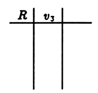
Make a table of \(R\) and the corresponding values of \(\nu _3\):

Now add a column to your table for the current through the lamp \(i=\nu _3/2\). Add rows to your table until you have found a value of \(R\) for which the lamp will glow. (\(i\) needs to be between 0.05 and 0.075 ampere.)


