4.9: Circuit Analysis
- Page ID
- 10117

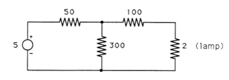
In this section we use the linear algebra we have developed to find the voltages and currents in a simple electrical circuit, such as the one shown in Figure 1. There are many reasons why this might be necessary; in this example we need to know the current flowing through the lamp to tell whether or not it will glow. Too little current will have no visible effect; too much current will cause the lamp to burn out. We will apply a few physical laws relating the voltages and currents in a circuit, turn these laws into systems of linear equations, and solve the equations for the voltages and currents.
Current, Voltage, and Resistance
We will use three physical quantities in our analysis of electrical circuits: current, voltage, and resistance. Current is the flow of electrical charge from one place to another. Electrons flowing through a wire or through some other electronic device comprise a current. Voltage is a difference in electric potential that makes electrons flow. Voltage is sometimes called electromotive force because it is like a “force” that moves electrons. Resistance is a property of the device through which the electron current flows. The lower the resistance of a device, the more easily current can flow through the device.
The analogy of water flowing through pipes can help you develop intuition about electrical circuits. In this analogy, electrical current corresponds to the flow rate of water. Voltage corresponds to the pressure that forces the water to flow, and resistance is the friction of flow. A small pipe would impede the flow of water more than would a large pipe, so the small pipe would correspond to a higher resistance. While this analogy can be helpful, keep in mind that electricity is not water. All analogies break down at some point.
We measure electrical current in amperes. The standard symbol for current is \(i\), and the direction of positive flow is indicated by an arrow on the circuit diagram. The arrow is for reference only; if the true current is in the opposite direction, we get negative values for \(i\). Because electrons are negatively charged, current is defined as flowing in the opposite direction as electron motion. But to reduce confusion, you should learn to think in terms of current rather than electron motion.
A point in a circuit where several devices are connected together is called a node. The conservation law for current says that “what flows in must flow out of a node,” a principle known as Kirchhoff's current law. Kirchhoff's current law states that the sum of all currents leaving a node is zero. In this law, a current entering the node is considered to be a negative current leaving the node.
Voltage is measured in volts and is usually written as \(\nu\) (or \(e\)). Since voltage is a difference in potential between two points (nodes), we can show it on a circuit diagram with a + and a –sign to indicate which two nodes we are comparing and which one of the nodes is considered negative. As with current, the markings are for reference only and we may end up with a negative value of \(\nu\).
In an electrical circuit, one node is usually chosen as a reference node and is considered to have a voltage of zero. Then the voltage at every other node is measured with respect to the reference node. This saves us the trouble of always specifying pairs of nodes for voltage measurements and marking + and – signs for each voltage. Other names for the reference node are common and ground.
A constant voltage source is a device that always forces the voltage between its two terminals to be a constant value. In Figure 1 the circle at the left represents a constant voltage source of 5 volts, so that the voltage at the upper (+) end is always exactly 5 volts higher than the voltage at the lower (-) end. A voltage source is something like a battery, but idealized. Real batteries do not maintain a constant output voltage under all conditions.
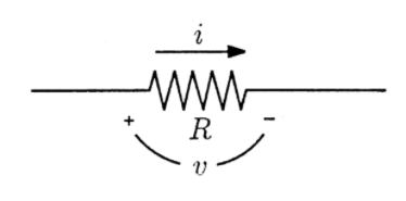
Resistance is measured in ohms and is denoted by \(R\). A resistor is shown as a zig-zag line in circuit diagrams and labeled with the value of its resistance in ohms. In this chapter we will consider only devices whose resistance is positive and the same in both directions. Ohm's law, also called the resistor law, relates the voltage and current in a resistor. For the resistor shown in Figure 2, with reference directions assigned to \(\nu\) and \(i\) as shown, Ohm's law is
\[\nu=i R \nonumber \]
Note that current flows from + to - through the resistor.
Ohm's law and Kirchhoff's current law are the only principles we need to write equations that will allow us to find the voltages and currents in the resistive circuit of Figure 1. We begin by choosing a reference node and assigning variables to the voltages at every other node (with respect to the reference node). These choices are shown in Figure 3.
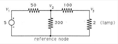
The constant voltage source forces \(\nu _1\) to be exactly 5 volts higher than the reference node. Thus
\[\nu _{1}=5 \nonumber \]
Next we write equations by applying Kirchhoff's current law to each node in the circuit (except the reference node and \(\nu _1\), whose voltages we already know). At the node labeled \(\nu _2\) are three paths for leaving current. The current leaving through the 50 ohm resistor can be found by Ohm's law, where the voltage across that resistor is \(\nu _2 − \nu _1\):
\[i_{50}=\frac{v}{R}=\frac{\left(v_{2}-v_{1}\right)}{50} \nonumber \]
For current leaving through the 300 ohm resistor, the voltage is \(\nu _2\). Pay careful attention to the sign; since we are interested in the current leaving the node labeled \(\nu _2\), Figure 4.14 indicates that to apply Ohm's law we should take the voltage as \(+ \nu _2 −\) reference = \(\nu _2 − 0 = \nu _2\). So
\[i_{300}=\frac{v_{2}}{300} \nonumber \]
For the 100 ohm resistor, we can write
\[i_{100}=\frac{\left(v_{2}-v_{3}\right)}{100} \nonumber \]
According to Kirchhoff's current law, the sum of these three leaving currents is zero:
\[\begin{align}
\quad \tfrac{\left(v_{2}-v_{1}\right)}{50}+\tfrac{v_{2}}{300}+\tfrac{\left(v_{2}-v_{3}\right)}{100}=0 \nonumber \\
\Rightarrow 6\left(v_{2}-v_{1}\right)+v_{2}+3\left(v_{2}-v_{3}\right)=0 \nonumber \\
\Rightarrow \qquad \quad -6 v_{1}+10 v_{2}-3 v_{3}=0 \label{}
\end{align} \nonumber \]
Notice that when we wrote the equation for the node labeled \(\nu _2\), the variable \(\nu _2\) had a + sign each time it occurred in the equation, while the others had a - sign. This is always the case, and watching for it can help you avoid sign errors. Now we apply Kirchhoff's current law at the node labeled \(\nu _3\) to get the equation
\[\begin{align}
\frac{\left(v_{3}-v_{2}\right)}{100}+\frac{v_{3}}{2}=0 \nonumber \\
\Rightarrow \quad\left(v_{3}-v_{2}\right)+50 v_{3}=0 \nonumber \\
\Rightarrow \quad 0 v_{1}-1 v_{2}+51 v_{3}=0 \label{}
\end{align} \nonumber \]
Note that this time it is \(\nu _3\) that always shows up with a + sign.
Equations 2, 6, and 7 give us a system of three equations in the three unknown variables \(\nu _1\), \(\nu _2\), and \(\nu _3\). We now write them in matrix form as
\[\left[\begin{array}{lll}
1 & 0 & 0 \\
-6 & 10 & -3 \\
0 & -1 & 51
\end{array}\right]\left[\begin{array}{l}
v_{1} \\
v_{2} \\
v_{3}
\end{array}\right]=\left[\begin{array}{l}
5 \\
0 \\
0
\end{array}\right] \nonumber \]
(MATLAB) Use MATLAB to solve Equation 8. You should find
\(\nu _1\) = 5.0000 volts
\(\nu _2\) = 3.0178 volts
\(\nu _3\) = 0.0592 volt
What is the determinant of the coefficient matrix \(A\)? Is the solution unique?
We can determine the current flowing through the lamp from \(\nu _3\) to ground in Example 1 by Ohm's law:
\[i=\frac{\nu}{R}=\frac{\nu _{3}}{2}=0.0296 \text { ampere } \nonumber \]
The visible effect will, of course, depend on the lamp. Let us assume that the specifications for our lamp indicate that 0.05 ampere or more is required before it will glow, and more than 0.075 ampere will cause it to burn out. In this case, our circuit would not make the lamp glow.
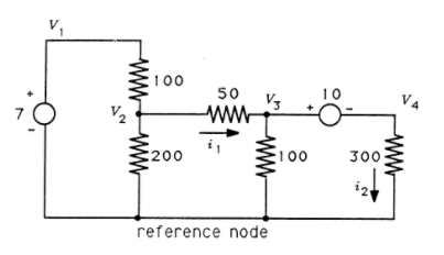
(MATLAB) Write and solve equations for the circuit in Figure 4. What are the voltages at the nodes labeled \(\nu _1\) through \(\nu _4\)? What is the current labeled \(i_1\)? And \(i_2\)?