
9.2: Polyphase Definition
- Page ID
- 25294

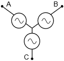
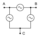
A polyphase system uses multiple current-carrying wires with multiple subgenerators, each with their own unique phase. This allows for considerable delivery of power to the load. The most popular scheme is the three-phase configuration. This can be visualized as three individual sine generators that are interconnected as shown in Figure \(\PageIndex{1}\). To the left is a Y (also known as wye or T) connected generator. To the right is a delta (i.e. \(\Delta\), and also known as \(\pi\) when drawn upside down) connected generator.
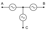
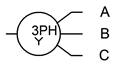
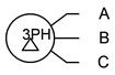
There are multiple ways of reproducing these generators on schematics. Some alternate forms for Y-connected generators are shown in Figure \(\PageIndex{2}\). The lone “tail” shown on the version to the right is a connection back to the common center of the three sub-generators. This is called the neutral line. It is not always used.
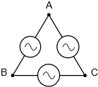
In Figure \(\PageIndex{3}\) we have some alternate forms for delta-connected generators. Delta generators do not have the optional fourth connection as there is no common center point. Also, note that the version on the left is drawn upside down (i.e., in the \(\pi\) configuration).
Of particular importance is the relative phase of each source. As the load will also have three segments or legs (a three-phase load), a consistent delivery of power demands that the three sources be spread equally over time. This means that each source is one-third of a cycle, or 120 degrees, out of phase with the other legs (i.e., leading one and lagging the other). This is shown in Figure \(\PageIndex{4}\). We shall only consider the case of balanced loads, that is, where each leg of the load is identical to the other legs.
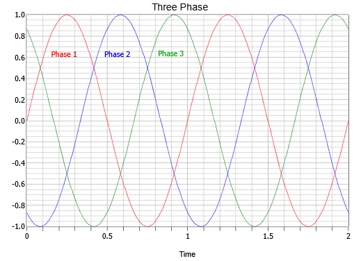
Notice the effectiveness of using the 120 degree stagger. At any time there is always either a peak or the shoulders of two adjacent peaks. These peaks can be either positive or negative polarity. This makes for a total of six peaks across the waveform's period. Therefore, a null is never more than 30 degrees away from the nearest peak. Indeed, when it is 30 degrees away, then it's precisely in between two peaks, and the value from each is the sine of 60 degrees (i.e., 30 degrees off of the peak at 90 degrees) or 86.6% of the peak value. Thus, it should be obvious that consistent power can be applied by this system. The inevitable car analogy is that we have gone from a two cylinder engine to a six cylinder engine when moving from single phase to three-phase.
There are several ways to connect three-phase generators to three-phase loads, as we shall see in the next section.