
4.9: Exercises
- Page ID
- 34244

4.9.1: Analysis Problems
1. Determine \(\beta\) if \(\alpha\) = 0.99.
2. Determine \(\alpha\) if \(\beta\) = 200.
3. Determine the currents for the circuit of Figure \(\PageIndex{1}\) if \(V_{BB} = 5\) V, \(V_{CC} = 20\) V, \(R_B = 200\) k\(\Omega\), \(R_C = 2\) k\(\Omega\), \(\beta\) = 100.
4. Determine the transistor voltages for the circuit of Figure \(\PageIndex{1}\) if \(V_{BB} = 5\) V, \(V_{CC} = 20\) V, \(R_B = 200\) k\(\Omega\), \(R_C = 2\) k\(\Omega\), \(\beta\) = 200.
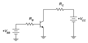
Figure \(\PageIndex{1}\)
5. Determine the LED current in the circuit of Figure \(\PageIndex{2}\) if \(V_{logic} = 5\) V, \(V_{CC} = 5\) V, \(V_{LED} = 2.1\) V, \(R_B = 3.6\) k\(\Omega\), \(R_C = 270\) \(\Omega\), \(\beta\) = 100.
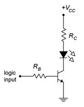
Figure \(\PageIndex{2}\)
6. Determine the LED current in the circuit of Figure \(\PageIndex{2}\) if \(V_{logic} = 0\) V, \(V_{CC} = 5\) V, \(V_{LED} = 2.1\) V, \(R_B = 3.6\) k\(\Omega\), \(R_C = 270\) \(\Omega\), \(\beta\) = 100.
7. Determine the LED current in the circuit of Figure \(\PageIndex{3}\) if \(V_{logic} = 5\) V, \(V_{EE} = 5\) V, \(V_{LED} = 2.2\) V, \(R_B = 2.7\) k\(\Omega\), \(R_C = 220\) \(\Omega\), \(\beta\) = 100.
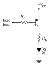
Figure \(\PageIndex{3}\)
8. Determine the LED current in the circuit of Figure \(\PageIndex{3}\) if \(V_{logic} = 0\) V, \(V_{EE} = 5\) V, \(V_{LED} = 2.2\) V, \(R_B = 2.7\) k\(\Omega\), \(R_C = 220\) \(\Omega\), \(\beta\) = 100.
9. Determine the LED current in the circuit of Figure \(\PageIndex{4}\) if \(V_{logic} = 3.6\) V, \(V_{CC} = 10\) V, \(V_{LED} = 2.3\) V, \(R_E = 270\) \(\Omega\), \(\beta\) = 200.
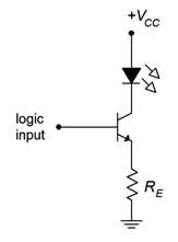
Figure \(\PageIndex{4}\)
10. Determine the LED current in the circuit of Figure \(\PageIndex{4}\). \(V_{logic} = 0\) V, \(V_{CC} = 10\) V, \(V_{LED} = 2.3\) V, \(R_E = 270\) \(\Omega\), \(\beta\) = 200.
11. Using the 2N3904 data sheet, determine \(V_{CE(sat)}\) if \(I_C = 30\) mA and \(I_B = 1\) mA.
12. Using the 2N3904 data sheet, determine the percent change in \(\beta\) if \(I_C = 10\) mA and the temperature rises from 25\(^{\circ}\)C to 125\(^{\circ}\)C.
13. Using the 2N3904 data sheet, determine the percent change in \(\beta\) if \(I_C = 40\) mA and the temperature drops from 25\(^{\circ}\)C to −55\(^{\circ}\)C.
4.9.2: Design Problems
14. Using Figure \(\PageIndex{1}\), determine a value for \(R_B\) to set \(I_C\) to 5 mA if \(V_{BB} = 5\) V, \(V_{CC} = 25\) V, \(R_C = 2\) k\(\Omega\), \(\beta\) = 100.
15. Using Figure \(\PageIndex{1}\), determine a value for \(R_C\) to set \(V_{CE}\) to 6 V if \(V_{BB} = 10\) V, \(V_{CC} = 25\) V, \(R_B = 330\) k\(\Omega\), \(\beta\) = 200.
16. For the circuit of Figure \(\PageIndex{2}\), determine a value for \(R_C\) to set the LED current to 15 mA. \(V_{logic} = 5\) V, \(V_{CC} = 5\) V, \(V_{LED} = 1.6\) V, \(R_B = 3.3\) k\(\Omega\).
17. For the circuit of Figure \(\PageIndex{3}\), determine a value for \(R_C\) to set the LED current to 20 mA. \(V_{logic} = 0\) V, \(V_{EE} = 5\) V, \(V_{LED} = 2.0\) V, \(R_B = 2.7\) k\(\Omega\).
18. For the circuit of Figure \(\PageIndex{4}\), determine a value for \(R_E\) to set the LED current to 25 mA. \(V_{logic} = 5\) V, \(V_{CC} = 9\) V, \(V_{LED} = 2.8\) V.
4.9.3: Challenge Problems
19. Determine the maximum and minimum values for \(I_C\) in the circuit of Figure \(\PageIndex{1}\) if all resistors have a 10% tolerance and \(\beta\) = ranges from 100 to 200. \(V_{BB} = 5\) V, \(V_{CC} = 20\) V, \(R_B = 200\) k\(\Omega\), \(R_C = 2\) k\(\Omega\).
20. Derive and draw a PNP non-saturating LED driver circuit.
4.9.4: Computer Simulation Problems
21. Simulate the circuit of Problem 3.
22. Simulate the circuit of Problem 5.
23. Simulate the circuit of Problem 7.
24. Verify the design of Problem 14 using a simulator.