
3.3: Clippers
- Page ID
- 25398

Sometimes it is useful to limit the maximum amplitude of a signal. This might be done for protection, for example when too large of an input signal might damage the following circuit. It might also be employed as a means of wave shaping, that is, morphing a signal into another shape. A good example is the purely aesthetic desire to emulate the sound of “fuzz” guitar. In the early days of rock music it was discovered that over-driving a guitar amplifier in an attempt to make it louder created considerable distortion and this produced a new and interesting sound quality. Technically, this is largely caused by the power stage of the amplifier reaching its maximum output level. Any portion of the waveform above this level is simply cut off or clipped1. The practical problem here is that the only way to achieve this sound is to crank up the guitar amplifier's volume to ten2 and live with the attendant high loudness level. Not too popular with the neighbors, that's for sure. In contrast, if the signal could be limited before the power amplifier stage in an attempt to mimic the clipping, the effect could be achieved without the resulting loudness. This proved to be so popular among guitarists that by the 1970s numerous companies were making “fuzz boxes” and “distortion pedals”, each with their own twist on the concept.
The simplest form of clipper places a diode (or two parallel diodes of opposing polarity) in parallel with the load. The diode will limit the output voltage swing to its forward turn-on potential; 0.7 volts for a silicon device. This circuit is somewhat limiting (pun intended) as you are stuck with a 0.7 volt limit value. What if we need to limit at some other potential, say 12 volts? While it is possible to stack a bunch of diodes in series to increase the limit point, a more flexible and practical approach involves biasing the diode with a DC source. This is called a biased diode clipper.
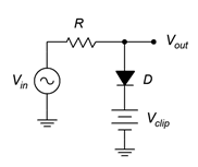
Figure \(\PageIndex{1}\): Biased positive clipper.
A biased diode clipper used to limit positive signals is shown in Figure \(\PageIndex{1}\). The operation is as follows. For any input signal that is less positive than the bias potential \(V_{clip}\), the diode will be in reverse-bias. This means that the diode branch presents a high resistance and is effectively removed from the circuit. Therefore, \(V_{in}\) flows through \(R\) to the output unimpeded. If the input signal exceeds by \(V_{clip}\) by approximately 0.7 volts, the diode turns on resulting in a very low internal resistance. As the internal resistance of the DC source is also very low, this creates a low impedance path to ground and results in a voltage divider with \(R\). As \(R\) is a much greater resistance value, virtually all of the input signal above the turn-on voltage will be dropped across \(R\), never reaching the output. Therefore, we can control or program the clip point by adjusting the bias voltage. Clipping will occur at approximately \(V_{clip}\) plus 0.7 volts, assuming a silicon diode is used.
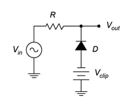
Figure \(\PageIndex{2}\): Biased negative clipper.
A negative biased clipper is shown in Figure \(\PageIndex{2}\). Both the diode and DC bias voltages have been flipped to the opposite polarity. The operation of this circuit is similar to the positive clipper. In this variant, the negative bias potential ensures that the diode is reverse-biased as long as the input level is more positive than \(V_{clip}\) minus 0.7 volts. Once the input signal goes below this voltage, the diode turns on creating the shorting path and limiting the output voltage.
A bipolar or dual-polarity clipper can be created by combining the positive and negative clippers. It is possible to limit the positive and negative swings independently, as illustrated in the following Example.
Example \(\PageIndex{1}\)
Determine the output signal for the circuit of Figure \(\PageIndex{3}\). The input voltage is a 12 volt peak sine wave at 100 Hz. \(D_1\) and \(D_2\) are silicon switching diodes. \(R = 10\) k\(\Omega\), \(V_1 = 4\) volts and \(V_2 = 8\) volts.
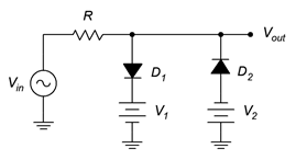
Figure \(\PageIndex{3}\): Dual clipper for Example \(\PageIndex{1}\).
First off, note that the precise value of \(R\) is unimportant here. It simply needs to be significantly larger than the on-resistance of the diodes. Based on our prior study of diode resistance in Chapter 2 (see the discussion around Figure 2.4.3) it is likely that the dynamic diode resistance will be under 100 \(\Omega\) once full turnon is reached. This resistance ratio is more than sufficient to create an effective voltage divider.
The positive clip level will be set by \(V_1\). Adding in the forward potential of \(D_1\) we arrive at 4.7 volts. The negative clip level will be set by \(V_2\). Including in the forward potential of \(D_2\) we arrive at −8.7 volts.
Thus, we expect to see a sine wave that is clipped at +4.7 volts and −8.7 volts. It should appear as a sort of lopsided cross between a sine wave and a square wave.
Computer Simulation
To verify and visualize our computations, the circuit of Example \(\PageIndex{1}\) is simulated with a transient analysis. The circuit schematic is shown in Figure \(\PageIndex{4}\). For the diodes, common 1N914 switching diodes are used.
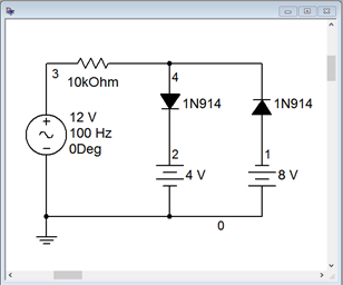
Figure \(\PageIndex{4}\): Simulation schematic for dual clipper of Example \(\PageIndex{1}\).
The results of the transient analysis are shown in Figure \(\PageIndex{5}\). The input waveform is shown in red while the output waveform is shown in blue. The input sine wave appears as expected with the specified 12 volt peak. The output follows the input perfectly for all values that are within the clip points. Beyond the clip points, the output voltage flattens. That is, it is limited to just below +5 volts (the programmed +4.7) and to just above −9 volts (the programmed −8.7 volts).
Careful inspection of the output waveform plot reveals that it is not perfectly flat at the voltage limits. In fact, there is a slight rounding that is most noticeable toward the transitions. This is due to the fact that the diodes do not turn on immediately. The dynamic resistance of the diodes change with the size of the signal. That is, the greater the input signal is above the clip point, the more current that will flow, and thus the dynamic resistance decreases, strengthening the effect of the voltage divider.
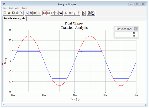
Figure \(\PageIndex{5}\): Transient analysis for dual clipper of Example \(\PageIndex{1}\).
References
1We will take a closer look at amplifier clipping in the chapters that cover power amplifiers.
2Or eleven, if you have a custom Spinal Tap amplifier.