
5.10: Differential and Common Modes
- Page ID
- 41049

\( \newcommand{\vecs}[1]{\overset { \scriptstyle \rightharpoonup} {\mathbf{#1}} } \)
\( \newcommand{\vecd}[1]{\overset{-\!-\!\rightharpoonup}{\vphantom{a}\smash {#1}}} \)
\( \newcommand{\dsum}{\displaystyle\sum\limits} \)
\( \newcommand{\dint}{\displaystyle\int\limits} \)
\( \newcommand{\dlim}{\displaystyle\lim\limits} \)
\( \newcommand{\id}{\mathrm{id}}\) \( \newcommand{\Span}{\mathrm{span}}\)
( \newcommand{\kernel}{\mathrm{null}\,}\) \( \newcommand{\range}{\mathrm{range}\,}\)
\( \newcommand{\RealPart}{\mathrm{Re}}\) \( \newcommand{\ImaginaryPart}{\mathrm{Im}}\)
\( \newcommand{\Argument}{\mathrm{Arg}}\) \( \newcommand{\norm}[1]{\| #1 \|}\)
\( \newcommand{\inner}[2]{\langle #1, #2 \rangle}\)
\( \newcommand{\Span}{\mathrm{span}}\)
\( \newcommand{\id}{\mathrm{id}}\)
\( \newcommand{\Span}{\mathrm{span}}\)
\( \newcommand{\kernel}{\mathrm{null}\,}\)
\( \newcommand{\range}{\mathrm{range}\,}\)
\( \newcommand{\RealPart}{\mathrm{Re}}\)
\( \newcommand{\ImaginaryPart}{\mathrm{Im}}\)
\( \newcommand{\Argument}{\mathrm{Arg}}\)
\( \newcommand{\norm}[1]{\| #1 \|}\)
\( \newcommand{\inner}[2]{\langle #1, #2 \rangle}\)
\( \newcommand{\Span}{\mathrm{span}}\) \( \newcommand{\AA}{\unicode[.8,0]{x212B}}\)
\( \newcommand{\vectorA}[1]{\vec{#1}} % arrow\)
\( \newcommand{\vectorAt}[1]{\vec{\text{#1}}} % arrow\)
\( \newcommand{\vectorB}[1]{\overset { \scriptstyle \rightharpoonup} {\mathbf{#1}} } \)
\( \newcommand{\vectorC}[1]{\textbf{#1}} \)
\( \newcommand{\vectorD}[1]{\overrightarrow{#1}} \)
\( \newcommand{\vectorDt}[1]{\overrightarrow{\text{#1}}} \)
\( \newcommand{\vectE}[1]{\overset{-\!-\!\rightharpoonup}{\vphantom{a}\smash{\mathbf {#1}}}} \)
\( \newcommand{\vecs}[1]{\overset { \scriptstyle \rightharpoonup} {\mathbf{#1}} } \)
\(\newcommand{\longvect}{\overrightarrow}\)
\( \newcommand{\vecd}[1]{\overset{-\!-\!\rightharpoonup}{\vphantom{a}\smash {#1}}} \)
\(\newcommand{\avec}{\mathbf a}\) \(\newcommand{\bvec}{\mathbf b}\) \(\newcommand{\cvec}{\mathbf c}\) \(\newcommand{\dvec}{\mathbf d}\) \(\newcommand{\dtil}{\widetilde{\mathbf d}}\) \(\newcommand{\evec}{\mathbf e}\) \(\newcommand{\fvec}{\mathbf f}\) \(\newcommand{\nvec}{\mathbf n}\) \(\newcommand{\pvec}{\mathbf p}\) \(\newcommand{\qvec}{\mathbf q}\) \(\newcommand{\svec}{\mathbf s}\) \(\newcommand{\tvec}{\mathbf t}\) \(\newcommand{\uvec}{\mathbf u}\) \(\newcommand{\vvec}{\mathbf v}\) \(\newcommand{\wvec}{\mathbf w}\) \(\newcommand{\xvec}{\mathbf x}\) \(\newcommand{\yvec}{\mathbf y}\) \(\newcommand{\zvec}{\mathbf z}\) \(\newcommand{\rvec}{\mathbf r}\) \(\newcommand{\mvec}{\mathbf m}\) \(\newcommand{\zerovec}{\mathbf 0}\) \(\newcommand{\onevec}{\mathbf 1}\) \(\newcommand{\real}{\mathbb R}\) \(\newcommand{\twovec}[2]{\left[\begin{array}{r}#1 \\ #2 \end{array}\right]}\) \(\newcommand{\ctwovec}[2]{\left[\begin{array}{c}#1 \\ #2 \end{array}\right]}\) \(\newcommand{\threevec}[3]{\left[\begin{array}{r}#1 \\ #2 \\ #3 \end{array}\right]}\) \(\newcommand{\cthreevec}[3]{\left[\begin{array}{c}#1 \\ #2 \\ #3 \end{array}\right]}\) \(\newcommand{\fourvec}[4]{\left[\begin{array}{r}#1 \\ #2 \\ #3 \\ #4 \end{array}\right]}\) \(\newcommand{\cfourvec}[4]{\left[\begin{array}{c}#1 \\ #2 \\ #3 \\ #4 \end{array}\right]}\) \(\newcommand{\fivevec}[5]{\left[\begin{array}{r}#1 \\ #2 \\ #3 \\ #4 \\ #5 \\ \end{array}\right]}\) \(\newcommand{\cfivevec}[5]{\left[\begin{array}{c}#1 \\ #2 \\ #3 \\ #4 \\ #5 \\ \end{array}\right]}\) \(\newcommand{\mattwo}[4]{\left[\begin{array}{rr}#1 \amp #2 \\ #3 \amp #4 \\ \end{array}\right]}\) \(\newcommand{\laspan}[1]{\text{Span}\{#1\}}\) \(\newcommand{\bcal}{\cal B}\) \(\newcommand{\ccal}{\cal C}\) \(\newcommand{\scal}{\cal S}\) \(\newcommand{\wcal}{\cal W}\) \(\newcommand{\ecal}{\cal E}\) \(\newcommand{\coords}[2]{\left\{#1\right\}_{#2}}\) \(\newcommand{\gray}[1]{\color{gray}{#1}}\) \(\newcommand{\lgray}[1]{\color{lightgray}{#1}}\) \(\newcommand{\rank}{\operatorname{rank}}\) \(\newcommand{\row}{\text{Row}}\) \(\newcommand{\col}{\text{Col}}\) \(\renewcommand{\row}{\text{Row}}\) \(\newcommand{\nul}{\text{Nul}}\) \(\newcommand{\var}{\text{Var}}\) \(\newcommand{\corr}{\text{corr}}\) \(\newcommand{\len}[1]{\left|#1\right|}\) \(\newcommand{\bbar}{\overline{\bvec}}\) \(\newcommand{\bhat}{\widehat{\bvec}}\) \(\newcommand{\bperp}{\bvec^\perp}\) \(\newcommand{\xhat}{\widehat{\xvec}}\) \(\newcommand{\vhat}{\widehat{\vvec}}\) \(\newcommand{\uhat}{\widehat{\uvec}}\) \(\newcommand{\what}{\widehat{\wvec}}\) \(\newcommand{\Sighat}{\widehat{\Sigma}}\) \(\newcommand{\lt}{<}\) \(\newcommand{\gt}{>}\) \(\newcommand{\amp}{&}\) \(\definecolor{fillinmathshade}{gray}{0.9}\)In working with RFICs it is convenient to use differential and common mode definitions, rather than odd and even mode definitions, as these directly relate to the differential circuits most commonly used in CMOS design. There are several reasons for this and one is that the most common type of amplifier with CMOS circuits is a differential amplifier where there are two input signal lines and two output signal lines and the actual signal is the differential signal which, in terms of voltage, is the difference of the two voltages on the lines. The situation is as shown in Figure \(\PageIndex{1}\)(a) where there are two signal conductors and a ground plane (at \(0\text{ V}\)). Here the differential voltage is \(V_{d} = (V_{1}−V_{2})\). The common mode voltage is \(V_{c} = \frac{1}{2}(V_{1}+V_{2})\) which will normally consist of a DC voltage and a usually small, and ideally zero, common mode signal which is the non-DC part of \(V_{c}\). Most CMOS circuits are designed so that the DC component of \(V_{d} = 0\). It is a quirk of history that microwave engineering and thus EM analysis used even- and odd-mode signals whose definitions differ by a factor of two from the definitions of common- and differential-mode signals. This section relates the two groups of signals and parameters for the common/differential mode group and the even/odd mode group.
The differential- and common-mode parameters of coupled lines can be derived from the odd- and even-mode parameters. The difference is in the definition of the voltage and currents in the modes as shown in Figure \(\PageIndex{1}\). The even mode is defined with \(V_{1} = V_{2} = V_{e}\) and \(I_{1} = I_{2} = I_{e}\), while for the common mode \(V_{1} = V_{2} = V_{c}\) and \(I_{1} + I_{2} = I_{c}\). Thus, in terms of the even-mode characteristic impedance, \(Z_{0e}\), the common-mode characteristic impedance is
\[\label{eq:1}Z_{0c}=\frac{1}{2}Z_{0e} \]
The odd mode is defined with \(V_{1} = −V_{2} = V_{o}\) and \(I_{1} = −I_{2} = I_{o}\), while for the differential mode \(V_{1} − V_{2} = V_{d}\) and \(I_{1} = −I_{2} = I_{d}\). Thus, in terms of the odd-mode characteristic impedance, \(Z_{0o}\), the differential-mode characteristic impedance is
\[\label{eq:2}Z_{0d}=2Z_{0o} \]
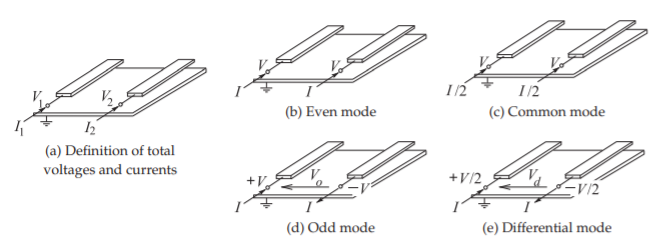
Figure \(\PageIndex{1}\): Definition of coupled-line modes.
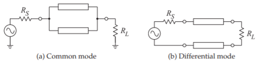
Figure \(\PageIndex{2}\): Driving configurations.
Other parameters remain unchanged. That is, the propagation constant, phase and group velocities, and wavelengths are the same for common and even modes, as they are for the differential and odd modes.
The driving and termination configurations for differential and common mode signals are shown in Figure \(\PageIndex{2}\). The reflectionless (i.e. matched) termination of coupled lines used in common mode is
\[\label{eq:3}R_{L}=Z_{0c}=\frac{1}{2}Z_{0e} \]
as in Figure \(\PageIndex{2}\)(a). The reflectionless termination of a differential line is
\[\label{eq:4}R_{L}=Z_{0d}=2Z_{0o} \]
as shown in Figure \(\PageIndex{2}\)(b).
A pair of coupled lines with common- and differential-mode characteristic impedances \(Z_{cC}\) and \(Z_{0d}\) respectively is loaded as shown in Figure 5.6.6(a) where the load has the two-port \(y\)-parameter matrix, \(\mathbf{Y}\). Find the common and differential-mode reflections. This example parallels Example 5.7.1 where even and odd modes were considered.
Solution
The analysis begins by writing out the expressions relating the traveling-wave and total voltages and currents at the termination.
\[\begin{array}{llll}{V_{c} =\frac{1}{2}(V_{1} + V_{2})}&{V_{d} = (V_{1} − V_{2})}&{I_{c} = (I_{1} + I_{2})}&{I_{d} = \frac{1}{2}(I_{1} − I_{2})}\\{V_{1} = (V_{1}^{+} + V_{1}^{−})}&{V_{2} = (V_{2}^{+} + V_{2}^{−})}&{I_{1} = (I_{1}^{+} + I_{1}^{−})}&{I_{2} = (I_{2}^{+} + I_{2}^{−})}\\{V_{1}^{+} = (V_{c}^{+} +\frac{1}{2}V_{d}^{+})}&{V_{2}^{+}= (V_{c}^{+} −\frac{1}{2} V_{d}^{+})}&{I_{1}^{+} = (\frac{1}{2} I_{c}^{+} + I_{d}^{+})}&{I_{2}^{+} = (\frac{1}{2} I_{c}^{−} − I_{d}^{+})}\\{V_{1}^{−} = (V_{c}^{−} +\frac{1}{2}V_{d}^{−})}&{V_{2}^{−} = (V_{c}^{−} −\frac{1}{2} V_{d}^{−})}&{I_{1}^{−} = (\frac{1}{2} I_{c}^{−} + I_{d}^{−})}&{I_{2}^{−} = (\frac{1}{2} I_{c}^{−} − I_{d}^{−})}\\{I_{c}^{+} = V_{c}^{+} /Z_{0c}}&{I_{c}^{−} = −V_{c}^{−} /Z_{0c}}&{I_{d}^{+} = V_{d}^{+}/Z_{0c}}&{I_{d}^{−} = −V_{d}^{−} /Z_{0d}}\end{array}\nonumber \]
At the termination
\[\begin{align}\left[\begin{array}{c}{I_{1}}\\{I_{2}}\end{array}\right]=\left[\begin{array}{c}{\frac{1}{2} I_{c}^{+} + I_{d}^{+} +\frac{1}{2} I_{c}^{−} + I_{d}^{−}}\\{\frac{1}{2}I_{c}^{+} − I_{d}^{+} + \frac{1}{2} I_{c}^{−} − I_{d}^{−}}\end{array}\right]&=\mathbf{Y}\left[\begin{array}{c}{V_{1}}\\{V_{2}}\end{array}\right]=\left[\begin{array}{cc}{y_{11}}&{y_{12}}\\{y_{21}}&{y_{22}}\end{array}\right]\left[\begin{array}{c}{V_{1}}\\{V_{2}}\end{array}\right]\nonumber \\ \label{eq:5}\left[\begin{array}{c}{\frac{1}{2}(V_{c}^{+} − V_{c}^{−})/Z_{0c} + (V_{d}^{+} − V_{d}^{−})/Z_{0d}}\\{\frac{1}{2}(V_{c}^{+} − V_{c}^{−})/Z_{0c} − (V_{d}^{+} − V_{d}^{−})/Z_{0d}}\end{array}\right]&=\left[\begin{array}{cc}{y_{11}}&{y_{12}}\\{y_{21}}&{y_{22}}\end{array}\right]\left[\begin{array}{c}{V_{c}^{+} +\frac{1}{2} V_{d}^{+} + V_{c}^{−} +\frac{1}{2} V_{d}^{−}}\\{V_{c}^{+} −\frac{1}{2} V_{d}^{+} + V_{c}^{−} −\frac{1}{2} V_{d}^{−}}\end{array}\right]\end{align} \]
The reflected even and odd modes have contributions from incident common and differential modes:
\[\label{eq:6}V_{c}^{−} = \Gamma_{Lc}V_{e}^{+} + C_{cd}V_{d}^{+}\quad\text{and}\quad V_{d}^{−} = \Gamma_{Ld}V_{d}^{+} + C_{dc}V_{c}^{+} \]
where \(\Gamma_{ce}\) and \(\Gamma_{Ld}\) are common- and differential-mode reflection coefficients, \(C_{dc}\) and \(C_{cd}\) describe coupling, and
\[\label{eq:7} \Gamma_{Lc}=\left.\frac{V_{c}^{-}}{V_{c}^{+}}\right|_{V_{d}^{+}=0}\quad\Gamma_{Ld}=\left.\frac{V_{d}^{-}}{V_{d}^{+}}\right|_{V_{c}^{+}=0}\quad C_{cd}=\left.\frac{V_{c}^{-}}{V_{d}^{+}}\right|_{V_{c}^{+}=0}\quad\text{and}\quad C_{dc}=\left.\frac{V_{d}^{-}}{V_{c}^{+}}\right|_{V_{d}^{+}=0} \]
\(\Gamma_{Lc}\) and \(C_{ed}\) are obtained by expanding Equation \(\eqref{eq:5}\) with \(V_{d}^{+} = 0\)
\[\begin{align} (V_{c}^{+} − V_{c}^{−})/Z_{0c} − 2V_{d}^{−}/Z_{0d} &= y_{11}(2V_{c}^{+} + 2V_{c}^{−} + V_{d}^{−}) + y_{12} (2V_{c}^{+} + 2V_{c}^{−} − V_{d}^{-}) \nonumber \\ \label{eq:8}\text{i.e. }\frac{V_{c}^{-}}{Z_{0c}} (1 + 2y_{11}Z_{0c} + 2y_{12}Z_{0c}) &= \frac{V_{c}^{+}}{Z_{0c}} (1 − 2y_{11}Z_{0c} − 2y_{12}Z_{0c}) −\frac{V_{d}^{-}}{Z_{0d}} (2 + y_{11}Z_{0d} − y_{12}Z_{0d}) \\ (V_{c}^{+} − V_{c}^{−})/Z_{0c} + 2V_{d}^{−})/Z_{0d} &= y_{21}( 2V_{c}^{+} + 2V_{c}^{−} + V_{d}^{−}) + y_{22}( 2V_{c}^{+} + 2V_{c}^{−} − V_{d}^{−}) \\ \label{eq:9}\text{i.e }\frac{V_{d}^{-}}{Z_{0d}}(−2 + y_{21}Z_{0d} − y_{22}Z_{0d}) &=\frac{V_{c}^{+}}{Z_{0c}} (1 − 2y_{21}Z_{0c} − 2y_{22}Z_{0c}) +\frac{V_{c}^{-}}{Z_{0c}} (−1 − 2y_{21}Z_{0c} − 2y_{22}Z_{0c})\end{align} \]
\(\Gamma_{Lc}\) is obtained by eliminating \(V_{d}^{−}\) by multiplying Equation \(\eqref{eq:9}\) by \((2 + y_{11}Z_{0d} − y_{12}Z_{0d})\) and subtracting it from Equation \(\eqref{eq:8}\) multiplied by \((−2 + y_{21}Z_{0d} − y_{22}Z_{0d})\):
\[\label{eq:10}V_{c}^{-}\frac{a}{Z_{0d}}=V_{c}^{+}\left.\frac{b}{Z_{0c}}\right|_{V_{d}^{+}=0}\quad\text{Thus}\quad\Gamma_{Le}=\frac{b}{a} \]
where
\[\begin{align} a&=(1 + 2y_{11}Z_{0c} + 2y_{12}Z_{0c})(−2 + y_{21}Z_{0d} − y_{22}Z_{0d})−(1 + 2y_{21}Z_{0c} + 2y_{22}Z_{0c})(2 + y_{11}Z_{0d} − y_{12}Z_{0d})\nonumber \\ \label{eq:11} &= −2 − Z_{0d}Y_{\Delta} − 4Z_{0c}Y_{\Sigma} − 4Z_{0c}Z_{0d}Y_{D} \\ b&=(1 − 2y_{11}Z_{0c} − 2y_{12}Z_{0c})(−2 + y_{21}Z_{0d} − y_{22}Z_{0d})−(1 − 2y_{21}Z_{0c}−2y_{22}Z_{0c})(2 + y_{11}Z_{0d} − y_{12}Z_{0d}) \\ \label{eq:12} & = −4 − Z_{0d}Y_{\Delta} + 4Z_{0c}Y_{\Sigma} + 4Z_{0c}Z_{0d}Y_{D} \end{align} \]
\[\begin{align}\label{eq:13} Y_{\Sigma}&= (y_{11} + y_{12} + y_{21} + y_{22}),\: Y_{\Delta} = (y_{11} − y_{12} − y_{21} + y_{22}),\:\:\text{ and }\:Y_{D} = (y_{11}y_{22} − y_{12}y_{21}) \\ \label{eq:14} \Gamma_{Le}&=\frac{b}{a}=\frac{4 + Z_{0d}Y_{\Delta} − 4Z_{0c}Y_{\Sigma} − 4Z_{0c}Z_{0d}Y_{D}}{4 + Z_{0d}Y_{\Delta} + 4Z_{0c}Y_{\Sigma} + 4Z_{0c}Z_{0d}Y_{D}}\end{align} \]
Compare this to the even-mode reflection coefficient, \(\Gamma_{Le}\), found in Example 5.6.6. Substituting \(Z_{0d} = 2Z_{0o}\) and \(Z_{0c} = \frac{1}{2}Z_{0e}\) in Equation \(\eqref{eq:14}\)
\[\label{eq:15}\Gamma_{Le}=\frac{4+2Z_{0o}Y_{\Delta} − 2Z_{0e}Y_{\Sigma} − 4Z_{0c}Z_{0d}Y_{D}}{4+2Z_{0o}Y_{\Delta} + 4Z_{0c}Y_{\Sigma} + 4Z_{0c}Z_{0d}Y_{D}}=\Gamma_{Le} \]
Find \(C_{cd}\) by expanding Equation \(\eqref{eq:5}\) with \(V_{c}^{+} = 0\):
\[\begin{align} −V_{c}^{−}/Z_{0c} + (2V_{d}^{+} − 2V_{d}^{−})/Z_{0d} &= y_{11}(V_{d}^{+} + 2V_{c}^{−} + V_{d}^{−}) + y_{12}(−V_{d}^{+} + 2V_{c}^{−} − V_{d}^{−}) \nonumber \\ \label{eq:16}\text{i.e. }\frac{V_{c}^{-}}{Z_{0c}}(1 + 2y_{11}Z_{0c} + 2y_{12}Z_{0c}) &=\frac{V_{d}^{+}}{Z_{0d}} (2 − y_{11}Z_{0d} + y_{12}Z_{0d}) −\frac{V_{d}^{-}}{Z_{0d}} (2 + y_{11}Z_{0d} − y_{12}Z_{0d}) \\ −V_{c}^{−}/Z_{0c} − (2V_{d}^{+} − 2V_{d}^{−})/Z_{0d} &= y_{21}(+V_{d}^{+} + 2V_{c}^{−} + V_{d}^{−}) + y_{22}(−V_{d}^{+} + 2V_{c}^{−} − V_{d}^{−}) \\ \label{eq:17}\text{i.e }\frac{V_{d}^{-}}{Z_{0d}}(−2 + y_{21}Z_{0d} − y_{22}Z_{0d}) &= −\frac{V_{d}^{+}}{Z_{0d}} (2 + y_{21}Z_{0d} − y_{22}Z_{0d}) −\frac{V_{c}^{-}}{Z_{0c}} (1 + 2y_{21}Z_{0c} + 2y_{22}Z_{0c})\end{align} \]
To eliminate \(V_{d}^{−}\) multiply Equation \(\eqref{eq:17}\) by \((2 + y_{11}Z_{0d} − y_{12}Z_{0d})\) and subtract it from Equation \(\eqref{eq:16}\) multiplied by \((−2 + y_{21}Z_{0d} − y_{22}Z_{0d})\):
\[\label{eq:18}\frac{V_{c}^{-}}{Z_{0c}}a=\frac{V_{d}^{+}}{Z_{0d}}c\quad\text{so that}\quad C_{eo}=\frac{c}{a}\frac{Z_{0c}}{Z_{0d}} \]
where \(a\) is as in Equation \(\eqref{eq:11}\) and
\[\begin{align} c &= (2 − y_{11}Z_{0d} + y_{12}Z_{0d})(−2 + y_{21}Z_{0d} − y_{22}Z_{0d})+(2 + y_{21}Z_{0d} − y_{22}Z_{0d})(2 + y_{11}Z_{0d} − y_{12}Z_{0d}) \nonumber \\ \label{eq:19} &= −2Z_{0d}Y_{E}\quad\text{where}\quad Y_{E} = (y_{11} − y_{12} + y_{21} − y_{22}) \end{align} \]
\[\label{eq:20}C_{cd}=\frac{4Z_{0c}Y_{E}}{4 + Z_{0d}Y_{\Delta} + 4Z_{0c}Y_{\Sigma} + 4Z_{0c}Z_{0d}Y_{D}}=C_{eo} \]
(which can be verified using the substitutions \(Z_{0d} = 2Z_{0o}\) and \(Z_{0c} =\frac{1}{2}Z_{0e}\)).
Similarly,
\[\label{eq:21}\Gamma_{Ld}=\frac{2 + Z_{0d}(y_{12} + y_{21}) − 2Z_{0c}Z_{0d}Y_{D}}{2 + Z_{0d}Y_{\Delta} + 4Z_{0c}Y_{\Sigma} + 2Z_{0c}Z_{0d}Y_{D}}=\Gamma_{Lo} \]
and
\[\label{eq:22}C_{dc}=\frac{-4Z_{0c}Y_{E}}{4 + Z_{0d}Y_{\Delta} + 4Z_{0c}Y_{\Sigma} + 4Z_{0c}Z_{0d}Y_{D}}=C_{cd}=C_{oe} \]