
4.11: Exercises
- Page ID
- 46116
\( \newcommand{\vecs}[1]{\overset { \scriptstyle \rightharpoonup} {\mathbf{#1}} } \)
\( \newcommand{\vecd}[1]{\overset{-\!-\!\rightharpoonup}{\vphantom{a}\smash {#1}}} \)
\( \newcommand{\dsum}{\displaystyle\sum\limits} \)
\( \newcommand{\dint}{\displaystyle\int\limits} \)
\( \newcommand{\dlim}{\displaystyle\lim\limits} \)
\( \newcommand{\id}{\mathrm{id}}\) \( \newcommand{\Span}{\mathrm{span}}\)
( \newcommand{\kernel}{\mathrm{null}\,}\) \( \newcommand{\range}{\mathrm{range}\,}\)
\( \newcommand{\RealPart}{\mathrm{Re}}\) \( \newcommand{\ImaginaryPart}{\mathrm{Im}}\)
\( \newcommand{\Argument}{\mathrm{Arg}}\) \( \newcommand{\norm}[1]{\| #1 \|}\)
\( \newcommand{\inner}[2]{\langle #1, #2 \rangle}\)
\( \newcommand{\Span}{\mathrm{span}}\)
\( \newcommand{\id}{\mathrm{id}}\)
\( \newcommand{\Span}{\mathrm{span}}\)
\( \newcommand{\kernel}{\mathrm{null}\,}\)
\( \newcommand{\range}{\mathrm{range}\,}\)
\( \newcommand{\RealPart}{\mathrm{Re}}\)
\( \newcommand{\ImaginaryPart}{\mathrm{Im}}\)
\( \newcommand{\Argument}{\mathrm{Arg}}\)
\( \newcommand{\norm}[1]{\| #1 \|}\)
\( \newcommand{\inner}[2]{\langle #1, #2 \rangle}\)
\( \newcommand{\Span}{\mathrm{span}}\) \( \newcommand{\AA}{\unicode[.8,0]{x212B}}\)
\( \newcommand{\vectorA}[1]{\vec{#1}} % arrow\)
\( \newcommand{\vectorAt}[1]{\vec{\text{#1}}} % arrow\)
\( \newcommand{\vectorB}[1]{\overset { \scriptstyle \rightharpoonup} {\mathbf{#1}} } \)
\( \newcommand{\vectorC}[1]{\textbf{#1}} \)
\( \newcommand{\vectorD}[1]{\overrightarrow{#1}} \)
\( \newcommand{\vectorDt}[1]{\overrightarrow{\text{#1}}} \)
\( \newcommand{\vectE}[1]{\overset{-\!-\!\rightharpoonup}{\vphantom{a}\smash{\mathbf {#1}}}} \)
\( \newcommand{\vecs}[1]{\overset { \scriptstyle \rightharpoonup} {\mathbf{#1}} } \)
\(\newcommand{\longvect}{\overrightarrow}\)
\( \newcommand{\vecd}[1]{\overset{-\!-\!\rightharpoonup}{\vphantom{a}\smash {#1}}} \)
\(\newcommand{\avec}{\mathbf a}\) \(\newcommand{\bvec}{\mathbf b}\) \(\newcommand{\cvec}{\mathbf c}\) \(\newcommand{\dvec}{\mathbf d}\) \(\newcommand{\dtil}{\widetilde{\mathbf d}}\) \(\newcommand{\evec}{\mathbf e}\) \(\newcommand{\fvec}{\mathbf f}\) \(\newcommand{\nvec}{\mathbf n}\) \(\newcommand{\pvec}{\mathbf p}\) \(\newcommand{\qvec}{\mathbf q}\) \(\newcommand{\svec}{\mathbf s}\) \(\newcommand{\tvec}{\mathbf t}\) \(\newcommand{\uvec}{\mathbf u}\) \(\newcommand{\vvec}{\mathbf v}\) \(\newcommand{\wvec}{\mathbf w}\) \(\newcommand{\xvec}{\mathbf x}\) \(\newcommand{\yvec}{\mathbf y}\) \(\newcommand{\zvec}{\mathbf z}\) \(\newcommand{\rvec}{\mathbf r}\) \(\newcommand{\mvec}{\mathbf m}\) \(\newcommand{\zerovec}{\mathbf 0}\) \(\newcommand{\onevec}{\mathbf 1}\) \(\newcommand{\real}{\mathbb R}\) \(\newcommand{\twovec}[2]{\left[\begin{array}{r}#1 \\ #2 \end{array}\right]}\) \(\newcommand{\ctwovec}[2]{\left[\begin{array}{c}#1 \\ #2 \end{array}\right]}\) \(\newcommand{\threevec}[3]{\left[\begin{array}{r}#1 \\ #2 \\ #3 \end{array}\right]}\) \(\newcommand{\cthreevec}[3]{\left[\begin{array}{c}#1 \\ #2 \\ #3 \end{array}\right]}\) \(\newcommand{\fourvec}[4]{\left[\begin{array}{r}#1 \\ #2 \\ #3 \\ #4 \end{array}\right]}\) \(\newcommand{\cfourvec}[4]{\left[\begin{array}{c}#1 \\ #2 \\ #3 \\ #4 \end{array}\right]}\) \(\newcommand{\fivevec}[5]{\left[\begin{array}{r}#1 \\ #2 \\ #3 \\ #4 \\ #5 \\ \end{array}\right]}\) \(\newcommand{\cfivevec}[5]{\left[\begin{array}{c}#1 \\ #2 \\ #3 \\ #4 \\ #5 \\ \end{array}\right]}\) \(\newcommand{\mattwo}[4]{\left[\begin{array}{rr}#1 \amp #2 \\ #3 \amp #4 \\ \end{array}\right]}\) \(\newcommand{\laspan}[1]{\text{Span}\{#1\}}\) \(\newcommand{\bcal}{\cal B}\) \(\newcommand{\ccal}{\cal C}\) \(\newcommand{\scal}{\cal S}\) \(\newcommand{\wcal}{\cal W}\) \(\newcommand{\ecal}{\cal E}\) \(\newcommand{\coords}[2]{\left\{#1\right\}_{#2}}\) \(\newcommand{\gray}[1]{\color{gray}{#1}}\) \(\newcommand{\lgray}[1]{\color{lightgray}{#1}}\) \(\newcommand{\rank}{\operatorname{rank}}\) \(\newcommand{\row}{\text{Row}}\) \(\newcommand{\col}{\text{Col}}\) \(\renewcommand{\row}{\text{Row}}\) \(\newcommand{\nul}{\text{Nul}}\) \(\newcommand{\var}{\text{Var}}\) \(\newcommand{\corr}{\text{corr}}\) \(\newcommand{\len}[1]{\left|#1\right|}\) \(\newcommand{\bbar}{\overline{\bvec}}\) \(\newcommand{\bhat}{\widehat{\bvec}}\) \(\newcommand{\bperp}{\bvec^\perp}\) \(\newcommand{\xhat}{\widehat{\xvec}}\) \(\newcommand{\vhat}{\widehat{\vvec}}\) \(\newcommand{\uhat}{\widehat{\uvec}}\) \(\newcommand{\what}{\widehat{\wvec}}\) \(\newcommand{\Sighat}{\widehat{\Sigma}}\) \(\newcommand{\lt}{<}\) \(\newcommand{\gt}{>}\) \(\newcommand{\amp}{&}\) \(\definecolor{fillinmathshade}{gray}{0.9}\)- An amplifier consists of three cascaded stages with the following characteristics:
Table \(\PageIndex{1}\)Stage 1 Stage 2 Stage 3 Gain (\(\text{dB}\)) \(-3\) \(15\) \(5\) NF (\(\text{dB}\)) \(3\) \(2\) \(2\) - What is the overall gain of the amplifier?
- What is the overall noise figure of the amplifier?
- Briefly describe the effect of a lossy filter on SNR. Consider signals at the input and output of the filter.
- What is the available noise power of a \(50\:\Omega\) resistor in a \(10\text{ MHz}\) bandwidth. The resistor is at standard temperature.
- A \(50\:\Omega\) resistor a \(20\:\Omega\) resistor are in shunt. If both resistors have a temperature of \(300\text{ K}\), what is the total available noise power spectral density of the shunt resistors?
- The thermal noise power at the output of a system is \(1\text{ fW}\) and the shot noise power is \(1\text{ fW}\). What is the available white noise power?
- A \(2\text{ GHz}\) amplifier in a \(50\:\Omega\) system has a bandwidth of \(10\text{ MHz}\), a gain of \(40\text{ dB}\), and a noise figure of \(3\text{ dB}\). The amplifier is driven by a circuit with a Thevenin equivalent resistance of \(50\:\Omega\) held at \(290\text{ K}\) (standard temperature). What is the available noise power at the output of the amplifier?
- A \(30\text{ dB}\) attenuator is terminated at Port \(\mathsf{2}\) in a matched resistor and both are at \(290\text{ K}\). What is the noise temperature at Port \(\mathsf{1}\) of the attenuator?
- A \(20\text{ dB}\) attenuator is terminated in a matched resistor and both are held at \(30^{\circ}\text{C}\). What is the noise temperature at the input of the attenuator in kelvin?
- The effective noise temperature at the coaxial output of an antenna is \(100\text{ K}\). The antenna is connected to a bandpass filter with a bandwidth of \(20\text{ MHz}\) and an insertion loss of \(1\text{ dB}\). [Parallels Examples 4.3.1 and 4.3.2]
- What is the available noise power in a \(20\text{ MHz}\) bandwidth at the output of the antenna?
- What is the noise figure of the bandpass filter (consider only the passband)?
- What is the excess noise power at the output of the filter? (Consider only the passband).
- What is the total available noise power in the passband at the output of the filter?
- A receive amplifier with a gain of \(30\text{ dB}\), a noise figure of \(2\text{ dB}\), and bandwidth of \(5\text{ MHz}\) is connected to an antenna which has a noise temperature of \(20\text{ K}\). [Parallels Example 4.3.1]
- What is the available noise power presented to the input of the amplifier in the \(5\text{ MHz}\) bandwidth (recall that the antenna noise temperature is \(20\text{ K}\)?
- If instead the input of the amplifier is connected to a resistor held at standard temperature, what is the available noise power presented to the input of the amplifier in the \(5\text{ MHz}\) bandwidth?
- What is the noise factor of the amplifier?
- What is the excess noise power of the amplifier referred to the its output?
- What is the effective noise temperature of the amplifier when the amplifier is connected to the antenna with a noise temperature of \(20\text{ K}\). That is, what is the effective noise temperature of the resistor in the Thevenin equivalent circuit of the amplifier output?
- A receive amplifier has a bandwidth of \(5\text{ MHz}\), a \(1\text{ dB}\) noise figure, a linear gain of \(20\text{ dB}\). The minimum acceptable SNR is \(10\text{ dB}\).
- What is the output noise power in \(\text{dBm}\)?
- What is the minimum detectable output signal in \(\text{dBm}\)?
- What is the minimum detectable input signal in \(\text{dBm}\)?
- A \(75\:\Omega\) attenuator has a loss of \(16\text{ dB}\) and is between a source with a Thevenin impedance of \(75\:\Omega\) and a load of \(75\:\Omega\).
- What is the noise power, \(N_{i}\), available from the \(75\:\Omega\) source resistor at standard temperature \((290\text{ K})\) in a \(1\text{ MHz}\) bandwidth?
- Now consider that the source is connected to the attenuator which is also connected to the load. If the source generates a modulated signal that is \(1\text{ MHz}\) wide and has an available power, \(S_{i}\), of \(10\text{ fW}\), what is SNR\(_{i}\) at the input to the attenuator at standard temperature?
- With the attenuator connected to the source, what is the Thevenin equivalent impedance looking into the output of the attenuator?
- Calculate the noise power, \(N_{o}\), available from the attenuator with the source attached at standard temperature \((290\text{ K})\) in a \(1\text{ MHz}\) bandwidth?
- What is the signal power, \(S_{o}\), delivered to the load?
- What is the SNR at the load, SNR\(_{o}\)?
- What is the noise factor of the attenuator?
- What is the noise figure of the attenuator?
- The system shown below is a receiver with bandpass filters, amplifiers, and a mixer. [Parallels Example 4.3.3]
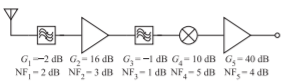
Figure \(\PageIndex{1}\)
- What is the total gain of the system?
- What is the noise factor of the first filter?
- What is the system noise factor?
- What is the system noise figure?
- An amplifier consists of three cascaded stages with the following characteristics:
Table \(\PageIndex{2}\)Stage 1 Stage 2 Stage 3 Gain \(10\text{ dB}\) \(15\text{ dB}\) \(30\text{ dB}\) NF \(0.8\text{ dB}\) \(2\text{ dB}\) \(2\text{ dB}\)
What is the noise figure (NF) and gain of the cascade amplifier? - The front end of a receiver for a cellular phone has a bandpass filter with a \(25\text{ MHz}\) passband and a loss in the passband of \(2\text{ dB}\) and is followed by two amplifier stages. The first stage has a gain of \(20\text{ dB}\) and a noise figure of \(0.5\text{ dB}\) and the second stage has a gain of \(60\text{ dB}\) and a noise figure of \(2\text{ dB}\).
- Sketch the system block diagram.
- What is the gain of the system?
- What is the noise figure of the filter?
- What is the noise figure of the system?
- The system is now connected to an antenna with an effective noise temperature of \(30\text{ K}\) that delivers a signal of \(10\text{ pW}\) to the bandpass filter. Determine the noise temperature at the output of the system and hence the output noise power in the \(25\text{ MHz}\) bandwidth. First calculate the excess noise temperature added by the system to the output.
- Determine the signal-to-noise ratio at the output of the front-end system.
- The RF front end of a communications unit consists of an amplifier followed by a mixer. The amplifier has a gain of \(20\text{ dB}\) and a noise figure of \(4\text{ dB}\). The mixer has a conversion loss of \(6\text{ dB}\) and a double-sideband noise figure of \(8\text{ dB}\).
- Why is the double-sideband noise figure sometimes used with a mixer but not with an amplifier?
- If the amplifier has sufficient bandwidth to amplify both the RF and image frequency, what is the noise figure of the cascade? Note that the overall noise figure is a single-sideband noise figure.
- The first stage of a two-stage amplifier has a linear gain of \(40\text{ dB}\) and a noise figure if \(3\text{ dB}\). The second stage has a gain of \(10\text{ dB}\) and a noise figure of \(5\text{ dB}\).
- What is the overall gain of the amplifier?
- What is the overall noise figure of the amplifier?
- A subsystem consists of a matched filter with an insertion loss of \(2\text{ dB}\) then an amplifier with a gain of \(20\text{ dB}\) and a noise figure, NF, of \(3\text{ dB}\).
- What is the overall gain of the subsystem?
- What is NF of the filter?
- What is NF of the subsystem?
- A subsystem consists of a matched amplifier with a gain of \(20\text{ dB}\) and a noise figure of \(2\text{ dB}\), followed by a \(2\text{ dB}\) attenuator, and then another amplifier with a gain of \(10\text{ dB}\) and NF of \(3\text{ dB}\).
- What is the overall gain of the subsystem?
- What is NF of the attenuator?
- What is NF of the subsystem?
- Consider a digitally modulated signal and briefly describe the impact of a nonlinear amplifier on the signal. You must include several negative effects. Use one or more diagrams.
- An amplifier has a linear gain of \(30\text{ dB}\) and an output-referred \(1\text{ dB}\) gain compression point of \(13\text{ dBm}\). What is the input-referred \(1\text{ dB}\) gain compression point of the amplifier?
- An amplifier has a linear gain of \(30\text{ dB}\) and an input-referred \(1\text{ dB}\) gain compression point of \(−30\text{ dBm}\). What is the output-referred \(1\text{ dB}\) gain compression point of the amplifier?
- An amplifier has an output power of \(10\text{ dBm}\) when the gain of a single tone is compressed by \(1\text{ dB}\). What is the maximum output power of an undistorted 64-QAM signal? (A 64-QAM signal which has a PMEPR of \(7.8\text{ dB}\). [Parallels Example 4.5.1]
- The input-referred \(1\text{ dB}\) gain compression point of an amplifier with a linear gain of \(30\text{ dB}\) is \(0\text{ dBm}\).
- What is the gain of the amplifier at \(1\text{ dB}\) gain compression?
- What is the output power at \(1\text{ dB}\) gain compression?
- Consider amplifying an 8-PSK signal with a PMEPR of \(3.3\text{ dB}\). What is the maximum output power of the undistorted 8-PSK signal? Maximum acceptable distortion is when the envelope peak is compressed by \(1\text{ dB}\) gain.
- The gain of an amplifier at the \(1\text{-dB}\) gain compression point is \(40\text{ dB}\) and the input power is \(−7\text{ dBm}\).
- What is the power of the amplifier’s output signal?
- If the power input to the amplifier is reduced to \(−20\text{ dBm}\), what is the amplifier’s output power now?
- Briefly describe intermodulation distortion with a a two-tone signal. Use a diagram.
- Briefly describe what is meant by \(1\text{ dB}\) gain compression. Use a diagram.
- A single-stage amplifier has a linear gain of \(16\text{ dB}\), an output \(1\text{ dB}\) gain compression point of \(10\text{ dBm}\), and an output-referred third-order intercept point \(\text{OIP3} = 30\text{ dBm}\). The noise floor at the output of the amplifier is \(−60\text{ dBm}\). The communication protocol has a minimum SNR, SNR\(_{\text{MIN}}\), of \(6\text{ dB}\).
- What is the dynamic range of the amplifier?
- What is the SFDR of the amplifier?
- A receiver system comprising a filter and two cascaded amplifiers has an overall linear gain of \(80\text{ dB}\), an output \(1\text{ dB}\) gain compression point of \(−10\text{ dBm}\), and an output-referred third-order intercept point, \(\text{OIP3} = 10\text{ dBm}\). The noise floor at the output of the amplifier is \(−80\text{ dBm}\). What is the spurious free dynamic range of the receiver?
- A power amplifier has a linear gain of \(20\text{ dB}\), an output \(1\text{ dB}\) gain compression point of \(30\text{ dBm}\), and an output-referred third-order intercept point \(\text{OIP3} = 60\text{ dBm}\). The noise floor at the output of the amplifier is \(−70\text{ dBm}\). What is the dynamic range of the amplifier if the required minimum SNR at the output is \(6\text{ dB}\)?
- A room-temperature two-stage amplifier in a receiver has a bandwidth of \(100\text{ MHz}\), a noise figure of \(3\text{ dB}\), a linear gain of \(32\text{ dB}\), and an output-referred third-order intercept point, \(\text{OIP3}\), of \(27\text{ dBm}\). The minimum SNR of the receiver system is \(16\text{ dB}\).
- What is the output noise power in \(\text{dBm}\)?
- What is the difference between the input-and output-referred spurious free dynamic ranges?
- What is the SFDR in \(\text{dB}\)?
- What is the difference between the input-and output-referred dynamic ranges?
- What is the minimum detectable output signal in \(\text{dBm}\)?
- What is the output-referred DR in \(\text{dB}\)?
- When determining the dynamic range of an amplifier the gain compression level is not used. Briefly discuss why.
Exercises by Section
\(†\)challenging, \(‡\)very challenging
\(§4.2\: 1, 2, 3, 4, 5, 6, 7, 8, 9, 10, 11\)
\(§4.3\: 12†, 13, 14, 15†, 16†, 17, 18, 19\)
\(§4.5\: 20, 21, 22, 23, 24, 25, 26, 27\)
\(§4.6\: 28, 29, 30, 31, 32\)
Answers to Selected Exercises
- (g) \(39.8\)
- (d) \(5.17\text{ dB}\)
- (b) \(3\text{ dB}\)
- (b) \(60\text{ dB}\)