
6.5: ODE and Excel model of a Simple Distillation Column
- Page ID
- 22395

Introduction
Distillation is a commonly employed separation technique bases on difference in volatilities. The modern form of distillation as is is known today may be credited to early Arab alchemist, Jabir ibn Hayyan and the development of one of his inventions, the alembic. The distillation apparatus is commonly referred to as a still and consists of a minimum of a reboiler in which mixture to be separated is heated, a condenser in which the vapor components are cooled back to liquid form, and a receiver in which the concentrated liquid component fractions are collected. Ideally, distillation is governed by the principles of Raoult’s Law and Dalton’s Law. Dalton’s Law states that for a mixture, the total vapor pressure is equal to the sum of the individual vapor pressures of the pure components which comprise this mixture. The relationship giving the vapor pressure of a volatile component in a mixture, PA, is Raoult’s Law and is governed by the following equation:
\[P_A = X_AP_A^o \nonumber \]
Where XA is the mole fraction of component A in the mixture and PA° is the vapor pressure of pure component A. This ideal model is based on a binary mixture of benzene and toluene but for other mixtures severe deviations from Raoult’s Law may be observed due to molecular interactions. For these aforementioned mixtures where the components are not similar the only accurate alternative is obtaining vapor-liquid equilibrium by measurement.
In simple distillation, two liquids with differing boiling points are separated by immediately passing the vapors from the reboiler to a condensing column which condenses the vapor components. As a result the distillate is not usually pure but its composition may be determined by Raoult’s Law at the temperature and pressure at which the vapors were boiled off. Consequently, simple distillation is usually used to separate binary mixtures where the boiling temperatures of the individual components are usually significantly different or to separate volatile liquids from non-volatile solids.
A reference of terms used in distillation reference are included at the end of this article.
Distillation Control
Distillation columns comprise an enormous amount of the separation processes of chemical industries. Because of their wide range of uses in these industries and because their proper operation contributes to product quality, production rates and other capital costs, it is clear that their optimization and control is of great importance to the chemical engineer. Distillation control becomes problematic because of the wide variety of thermodynamic factors stemming from the separation process. For example:
- Separations deviate from linearity of equations as product purity increases.
- Coupling of process variables occurs when compositions are controlled.
- Disturbances occur due to feed and flow agitation
- Efficiency changes in trays lead to non-steady state behavior.
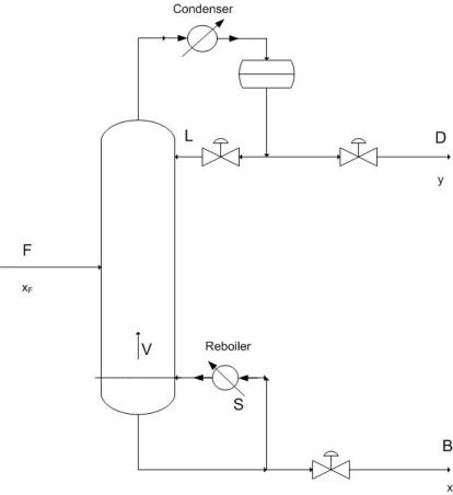
To improve upon distillation control you must be able to characterize these potential problems and realize when they occur because they lead to dynamic behavior of the column. Of key importance to control is the maintenance of material and energy balances and their due effects on the column. Shown below is a schematic of a simple binary distillation column. Using the material balance formulas
\[\dfrac{D}{F} = \dfrac{z-x}{y-x} \nonumber \]
where \(z\), \(x\), and \(y\) are the feed, bottoms and distillate concentrations respectively, you find that as \(D\) (Distillate) increases, its purity decreases. This leads to the idea that purity level varies indirectly with the flow rate of that product. Energy input is also key because it determines the vapor flow rate (\(V\)) up the column which has direct effects on the \(L/D\) ratio (reflux ratio) and hence relates to an increase in the amount of separation occurring. To summarize, energy input determines the amount of separation, while material flow relates the ratio of separation in the products.
Vapor liquid dynamics within the column also contributes to the theory behind process control because of a few important relations. Changing V (by changing the reboiler energy), causes an extremely rapid response in the overhead composition, while changing the reflux ratio requires a longer response to its effect on the reboiler.
In lower pressure columns, a phenomena known as entrainment or flooding occurs in which liquid is blown up into trays instead of dropping down into trays. This significantly decreases separation efficiency and therefore less product gain occurs. Using a packed column in these low pressure applications provides greater efficiency over tray columns and also allows for the faster accomplishment of a steady state profile. Controlling the occurrence of entrainment in either case is another crucial aspect which should be recognized when designing control systems for columns.
Regulatory Controls
For the distillation process it is imperative that regulatory controls such as level, flow, and pressure controllers are functioning properly to further ensure the effectiveness of the product composition controllers.
In terms of regulatory control, level controls are used to maintain specified levels in the reboiler, accumulator, and in the case of a distillation column with two columns due to high tray numbers for a single column, also maintain the level in an intermediate accumulator. Inept use of level controls may lead to problems elsewhere in the distillation process. For example, poor level control on the accumulator and reboiler may lead to problems with composition control for material balance control configurations. Also if the reboiler duty is maintained by one of these level controllers and the controller causes oscillation in the reboiler, consequently cycling may also occur in column pressure.
Flow controllers are used to manipulate and maintain desired flow rates of the reflux, distillate and bottoms products, and the heating medium employed in the reboiler. The setpoints of this specific type of controller is determined by the various composition and level controllers in the process.
Pressure controls are located to the top of the distillation column in the distillate vicinity. Here the column overhead pressure, caused by the accumulation of components in the vapor phase, acts as an integrator causing a change in the level of the accumulator. This pressure may be controlled using a variety of methods.
Pressure Control through Condenser Operation
- Maximize cooling water flow rate to the condenser (operate at minimum column pressure)
- Adjust the rate of condensation of the overhead (for example by adjusting the flow rate of refrigerant to the condenser)
- Adjust level of liquid in the condenser (changes heat transfer area)
Pressure Control through Accumulator Operation
- Purge vapor from the overhead accumulator
- Directly changing amount of material phase (for example by pumping in inerts)
Composition and Constraint Control
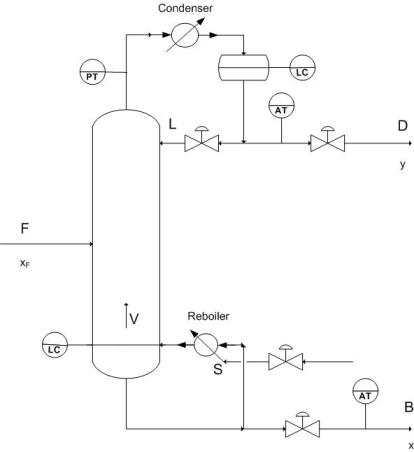
Because distillation requires a desired product concentration or flowrate, constraint control is used to ensure the desired operation conditions by having setpoints designated for the requirements of the system. The constraint is usually a concentration and the control of this concentration can vary depending on the application. In almost all industry applications only one product concentration is controlled, while the other is allowed to vary. This is known as Single Composition control and is much easier to achieve and maintain than the Dual composition control which specifies both product concentrations. The advantage to Dual Control however being increased energy efficiency because of increased separation. P&ID of common control placement used for composition control are shown below. Control lines are not included in this diagram because of the various number of control possibilites for a system.
Setting constraints on a column allows for proper control of the product as well as points to issues of safety and maintenance. The most common constraint controls are in the maximum reboiler and condenser duty which results from a number of variables including fouling , improper valve sizing, and excessive increases in feed. Other common constraints are flooding and weeping points which indicate incorrect \(L/V\) ratios and can be compensated for by adjusting the pressure drop across the column.
The most common adjustments for constraint control involve changing the reboiler duty to satisfy the constraints and almost always follow with subsequent fall back mechanisms to ensure product quality.
- Ensuring single composition control
- Reducing feed rate
- Increasing product purity setpoints
Effective Distillation Control
Before doing an in depth analysis of distillation control, it is of paramount importance that the following basics are attended to.
- Firstly, ensure that regulatory controls are indeed functioning congruously.
- For changes in reflux temperature, employ the use of reflux controls.
- Make sure to check and evaluate analyzer deadtime, accuracy, and reliability. This is required to account for the lagtime from the product composition analyzer when using feedback control to control feed flow, reflux ratio and reboiler power. Refer to for deadtime. To select proper analyzer refer to
- Ensure that any thermistors or RTD’s employed to measure tray temperatures for composition inference are fully operational and correctly situated. Care should be taken here to ensure that pressure corrected temperatures are used. Refer to the following for temperature sensors
- When streams such as D, B, L, and V are used as manipulated variables for composition control, they should be changed with respect to the measured feed rate when column feed rate changes are a common disturbance.
| Control Parameter | Example of Control Method |
|---|---|
| Distillate flow rate (D) | Flow controller (Setpoint controlled by accumulator level) |
| Bottoms flow rate (W) | Flow controller (Setpoint controlled by level in bottom of column) |
| Reflux flow rate (LD) | Flow controller (Setpoint controlled by top tray temperature) |
| Reboiler Steam flow rate | Flow controller (Setpoint controlled by bottoms composition analyzer) |
| Feed flow rate | Flow controller (Setpoint manually entered based on unit operations) |
| Distillate purity (xD) | Reflux flow controller (Setpoint controlled by top tray temperature) |
| Bottoms purity (xW) | Steam flow controller (Setpoint controlled by online analyzer) |
| Column pressure | Purge flow controller (Setpoint controlled by column pressure) |
Control Problems and Disturbances
Feed Composition & Feed Flow Upsets
In order to properly determine the ultimate product purity and flow you must consider the impact of disturbances in the column system. The most significant, however most easily remedial of these disturbances is a feed composition upset, in which there is a change in the feed composition resulting in a major disturbance in the product composition. Hence, configuration of a distillation column must consider the control regulations of such a feed upset. Feed flow upsets are regulated using ratio control of L/F, D/F, V/F and B/F through level and reflux ratio sensors.
Feed and Reflux Enthalpy Disturbances
Feed Enthalpy upsets become an issue for columns operating at low reflux ratios and cause a large deviation from expected product concentrations due to the changes in vapor and liquid flowrates in the column. The usual compensation for this is using a feed heat exchanger to control the proper enthalpy to the column. In most cases, the feed is preheated before entering the column. By adjusting the duty of the preheater (i.e. decreasing or increasing the heating medium flow rate), a constant vapor/liquid ratio in the feed can be maintained. Rapid changes to the external conditions of a column, (especially large temperature deviations in rainstorms) can cause a subcooled reflux, changing the composition of the products. Reflux control can amend this properly.
Steam and Column Pressure Upsets
The most severe disturbance occurring in a distillation column occurs when there is a loss of steam pressure in the reboiler. A sharp drop in steam pressure results in a drop in reboiler effectiveness and therefore a huge increase in the impurity of the product. This can be avoided using an override control loop for this particular occurrence. Due to the effect of pressure on the relative volatility of the components in the system, a disturbance in column pressure leads to altered product quality. This can be effectively maintained by a composition controller to compensate for these pressure differences.
ODE Modeling of a Distillation Column
There are two methods used for modeling a distillation column: dynamic modeling and steady state modeling. The key difference between the models is that dynamic modeling is used to monitor changes in the distillation column as a function of time, while the steady state model looks at a given set of conditions at one particular time (i.e. when the column is at steady state).
Dynamic Model
Dynamic modeling of a distillation column may be used for a variety of different reasons: monitoring variations in the column as a result of feed changes, to predict the effects of tray fouling, and to predict when flooding with occur. The dynamic model allows the user to improve distillation control by being able to deal with disturbances that cause upsets to the column's normal operation.
The algorithm for developing a dynamic distillation column model is as follows:
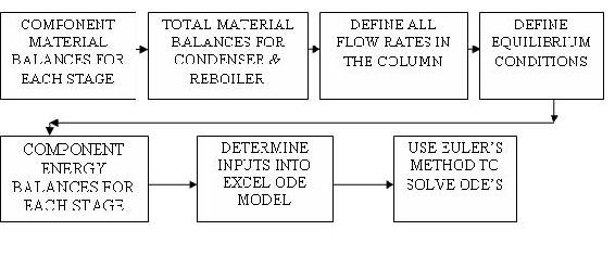
Step 1) Write component material balance for each stage in the column.

Component material balance for all stages, except the feed tray, overhead condenser, and reboiler:
\[\frac{d M_{i} x_{i}}{d t}=L_{i-1} x_{i-1}+V_{i+1} y_{i+1}-L_{i} x_{i}-V_{i} y_{i} \nonumber \]
Assumption: For simplicity, accumulation in the each stage is constant;
\[\frac{d M_{i}}{d t}=0 \nonumber \]
Simplified component material balance for each stage (only composition changes with time):
\[M_{i} \frac{d x_{i}}{d t}=L_{i-1} x_{i-1}+V_{i+1} y_{i+1}-L_{i} x_{i}-V_{i} y_{i} \nonumber \]
The following are examples of equations used in the Excel Interactive ODE Distillation Column Model, which are provided to help the user understand how the model works.
ODE used to solve for the liquid composition leaving tray 2 (rectifying section):
\[\frac{d x_{2}}{d t}=\frac{1}{M_{2}}\left[L_{1} x_{1}+V_{3} y_{3}-L_{2} x_{2}-V_{2} y_{2}\right] \nonumber \]
ODE used to solve for the liquid composition leaving tray 5 (stripping section):
\[\frac{d x_{5}}{d t}=\frac{1}{M_{5}}\left[L_{4} x_{4}+V_{6} y_{6}-L_{5} x_{5}-V_{5} y_{5}\right] \nonumber \]
Overhead condenser component balance:
\[\frac{d x_{D}}{d t}=\frac{1}{M_{D}}\left[V_{1}\left(y_{1}-x_{D}\right)\right] \nonumber \]
Feed tray component balance:
\[\frac{d x_{3}}{d t}=\frac{1}{M_{3}}\left[L_{2} x_{2}+V_{4} y_{4}-L_{3} x_{3}-V_{3} y_{3}\right] \nonumber \]
Reboiler component balance:
\[\frac{d x_{W}}{d t}=\frac{1}{M_{W}}\left[L_{6} x_{6}-W x_{W}-V_{7} y_{7}\right] \nonumber \]
Step 2) Write total material balances around condenser and reboiler
Condenser material balance:
- Assumption 1: Total condenser (all vapor from the top of the column is condensed into a liquid).
- Assumption 2: Overhead accumulator liquid level remains constant.
\[D=\left[V_{1}+L_{D}\right] \nonumber \]
Reboiler material balance:
\[W=[F-D] \nonumber \]
For these equations to work, the user must specify:
- reflux flow rate (mol/min)
- bottoms flow rate (mol/min).
Step 3) Define all flow rates
Vapor Leaving Feed Stage:
\[V_{3}=V_{4}+F\left(1-q_{F}\right) \nonumber \]
Liquid Leaving Feed Stage:
\[L_{3}=L_{2}+F\left(q_{F}\right) \nonumber \]
Vapor flow rates in stripping section:
Assumption: Equimolal overflow for vapor in stripping section
\[V_{4}=V_{5}=V_{6}=\left(V_{7}\right) \nonumber \]
Vapor flow rates in rectifying section:
Assumption: Equimolal overflow for vapor in rectifying section
\[V_{1}=V_{2}=\left(V_{3}\right) \nonumber \]
Liquid flow rates in rectifying section:
Assumption: Equimolal overflow for liquid in rectifying section
\[L_{2}=L_{1}=\left(L_{D}\right) \nonumber \]
Liquid flow rates in stripping section:
Assumption: Equimolal overflow for liquid in stripping section
\[L_{6}=L_{5}=L_{4}=\left(L_{3}\right) \nonumber \]
Step 4) Define equilibrium conditions
The binary system used in the Excel ODE model is a benzene-toluene system. The equilibrium data for this system was put in the model and the relative volatilities were calculated for various equilibrium compositions.
Relative Volatility (from equilibrium data):
\[\alpha=\frac{y_{\text {benzene }} \chi_{\text {toluene }}}{\chi_{\text {benzene }} y_{\text {toluene }}} \nonumber \]
where α is defined as the relative volatility of the two components in the system.
These relative volatilities were plotted against temperature and linear regression was used to fit the data.
Relative volativity as a function of temperature:
\[\alpha=[-0.009 T+3.3157] \nonumber \]
This equation models how the separation changes on each tray as a function of tray temperature, which decreases up the column.
Equilibrium Vapor Composition for each stage:
Assumption: Trays in the Column are 100% efficient (vapor and liquid leaving a tray are in equilibrium)
\[y_{i}=\frac{\alpha x_{i}}{1+(\alpha-1) x_{i}} \nonumber \]
Replacing alpha with the temperature dependent equation shows how tray temperature affects the amount of benzene in the vapor leaving each tray.
Step 5) Write component energy balances for each stage.
The ODE energy balances are essential for the dynamic model to run properly. Mass transfer occurs within the column because the temperature varies from the top of the column to the bottom thereby allowing separation of the components in the system.
Since the energy input into the column is added in the reboiler, the reboiler ODE is the first equation entered in the model. In our model, this is given as:
\[\frac{d T_{7}}{d t}=\frac{1}{M_{W}}\left[L_{6} x_{6}-W x_{W}\right]\left[T_{6}-T_{7}\right]+\frac{q_{r}}{M_{W} c_{p}} \nonumber \]
The next step is adding energy balances for each subsequent stage in the distillation column. The only stage in the column which has a slightly different energy ODE is the feed stage, given by:

The last energy balance is around the condenser.
Assumption: Reflux return temperature is constant (overhead condenser duty varies to compensate for this).
Step 6) Determine inputs into ODE model
Once all of the equations have been put into the model, all remaining unknown variables must be placed in a section so that the user can specify these input values when running the model. For the Excel ODE distillation model, the users inputs include:
- Feed flow rate
- Mole fraction of light key in the feed
- Reflux flow rate
- Condenser, reboiler, and tray levels
- Phase of the feed (q-value)
- Feed temperature
- Integration step size
To model effects of disturbances, the user may also change these input values:
- Feed flow after 200 time steps
- Feed composition after 600 time steps
Step 7) Use Euler's Method to solve the ODE's
This step involves using Euler's method. to integrate each ODE over each timestep in the interval to solve for the parameter value at the next time step. Creating a plot of these values versus time allows the user to see how changes in the input values effect parameters such as distillate and bottoms composition or flowrates.
Additional Considerations for Dynamic Distillation Modeling
The Interactive Excel ODE Distillation Column Model does not take into account heat effects within or surrounding the column. It may be beneficial in modeling an actual column to determine the optimal temperatures that feed and reflux should enter at to achieve the greatest possible separation. The energy input into the reboiler is another consideration that may need to be modeled for economic purposes.
Also, to tune the dynamic distillation model with greater precision, additional parameters and equations may be added. One example of this would be to add a KD or KU input value to control the levels in the bottom of the column or overhead condenser.
Steady State Model
The steady state model which is described by using a McCabe-Thiele diagram shows the theoretical stages in a binary component distillation column. An example of a McCabe-Thiele diagram is shown below.
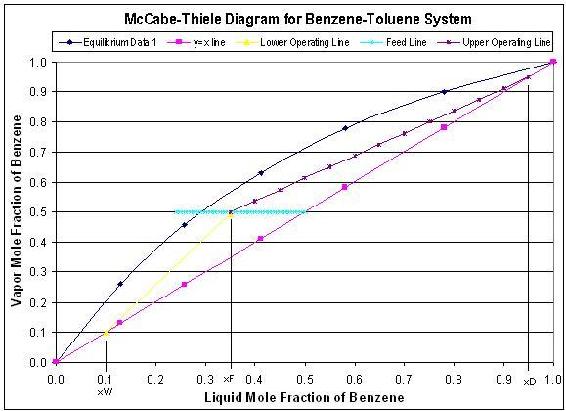
The upper operating line is a graphical representation of the vapor/liquid dynamics in each stage in the rectifying section of the column (above the feed stage), while the lower operating line represents the vapor/liquid dynamics in the stripping section of the column (below the feed stage). The starting point of the upper operating line represents the distillate composition and the bottom point of the lower operating line represents the bottoms compostion. The feed line shows the entering feed composition as well as whether the feed is vapor, liquid, or a combination of the two. To develop this steady state model, one must know the components in the system, so that equilibrium data can be obtained. Also, this model requires that the following parameters must be known:
- reflux ratio
- distillate composition
- bottoms composition
- feed composition
- feed phase
The general equations used in the steady state model are given in the table below:
Media:EquationsforODEModeling.doc
The McCabe-Thiele diagrams are excellent for modeling steady state operation, but they do not describe how disturbances affect the column operation. For each change in a particular parameter, a separate McCabe-Thiele diagram must be made. The dynamic model, although more complex than the steady state model, shows how a column operates during start-ups, when disturbances occurs, and where steady state conditions occur. Therefore, the dynamic ODE model of a distillation column can allow the user to how product purities and flow rates change with time.
Glossary of Terms
- Mi = Molar holdup on tray i
- Li − 1 = Liquid molar flowrate into tray i
- Li = Liquid molar flowrate leaving tray i
- Vi + 1 = Vapor molar flowrate entering tray i
- Vi = Vapor molar flowrate leaving tray i
- xi = mole fraction of light component in the Liquid phase of Tray i
- yi = mole fraction of light component in the Gas phase of Tray i
- B = Bottoms flowrate
- D = Distillate flowrate
- f = Feed flow rate
 = Relative volatility of Benzene-Toluene system.
- q = Vapor Liquid compostion value
Our Excel Distillation Model
Below you will find a link for our distillation model in Excel. It is an exceptionally large download so it may take some time if you are not using a high speed internet connection. Because it takes some time for the iterations to run to completion, calculations are not continuous within the spreadsheet. Be patient as it may take a few seconds for the calculations to run when operational parameters change. Also, because of the nature of the iterative process Excel uses to determine the cell values, large deviations may cause the model to crash resulting in #Error# for many cells. If this occurs, close the model and re-open it from the website to try different parameters.
In order to demonstrate dynamic changes occuring during operation, step changes are incorporated into the Excel model. To show the effects of a feed change, input the change into cell C-18. This change will occur at t=2min for a length 2 minutes and then the feed flowrate will revert back to the original value. To demonstrate a change in the feed compostion at t= 6min, input the change into cell C-19 on the Excel model. This compostion change will be constant over the remainder of the time and will not revert to the previous value. Notice the changes occuring in the graphs as these step changes occur. The Excel model can be found here => Media:ODEDistillationModel-Final.zip
This model has a specified control range because typical operation of distillation columns requires operation within a specific range of values where input parameters marginally vary. It is recommended to use the following variables for the initial model.
- Feed Flow to Column = 50.00
- Feed Composition (xF) = 0.5
- Reflux Flow = 15
- Bottoms Flow @ T= 0 = 35.00
- Mtray = 10
- Mcondenser = 50
- Mreboiler = 50
- qF = 0.4
- Feed Temperature = 80
- Reflux Temp = 80
- Initial Column Temp = 80
- Qreboiler = 100
Avoid extreme changes in the initial values, otherwise a significant error may occur causing the model to crash. The principal cause of this is due to the heat effects which are taken into account in the model and the fact that the number of trays on the column is set at 6.
Terms Commonly Used in Distillation
- Active tray area: The region of the tray where the upward moving vapor comes into contact with the downward flowing liquid (where the mass transfer occurs)
- Downcomer: Area on side of trays where liquid flows down through the distillation column
- Disturbance (wrt distillation): Any minor change in the distillation column caused by an external or internal source that causes product variability
- Flooding: Liquid from the active tray area is carried up into the vapor stream (occurs at low L/V ratios)
- Ratio Control: Controlled ratio of two manipulated variables
- Tray Fouling: Active area of tray is deminished, thus reducing separation efficiency within the column
- Upset: Any major change in the distillation caused by an external source that produces erratic column operation that requires manual override to gain control
- Weeping Points: Liquid from the active tray area seeps downward through the tray instead of flowing through the downcomer (occurs at high L/V ratios)
Using the Excel Model of a Distillation Column posted above, see how a change in the feed concentration upsets the steadystate equilibration of the inital flow and how the column thereby adjusts to a change in feed composition at the time step indicated. Then determine the effect of changing the feed flowrate and reflux flow at the indicated times during the time the column is running. Also, determine the effect of making a larger step size for use in Eulers method.
Remember: an excessive change may cause the distillation column to blow up, so take care in determining reasonable changes. Input the changes in the flowrate or concentration into C17-C20 of the spreadsheet. Input the new step size in cell D21.
Solutions
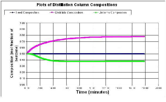
The normal concentration output for the distillation column is shown below. Feed flow rate is 50 mol/min, reflux flowrate is 15 mol/min, feed composition is 0.5 mol fraction of the light component. Step size is 0.01 minutes.
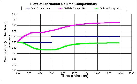
Students should see that an impulse change in flowrates does not really change the steady state profile of the column. However, a change in feed concentration will cause the column to jump and then equilibrate for the new concentration values. Below is a graph with a change in the feed flowrate to 100 mol/min, and a concentration change to 0.6 of the light component.
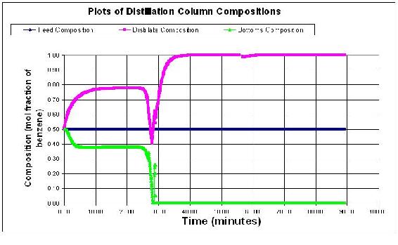
Larger step sizes will cause the model to crash because the error associated with the derivatives becomes larger with each derivative taken. Below the step size is 0.05 minutes. At some point the derivatives become uselsess data and therefore the distillation column model blows up with outrageous values as shown below.
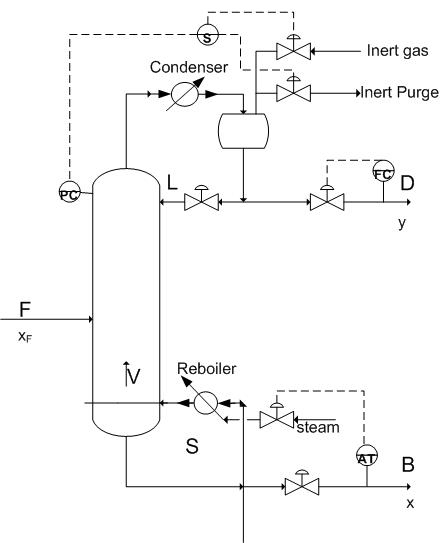
As a new hire at a specialty chemical company you are placed on project where you are asked to design and specify the controls on a state of the art distillation column used to separate a binary system. Your supervisor gives you a few clues to the control mechanism based on the chemistry occurring.
- The salable component is the heavy component and the mixture has a low relative volatility.
- The light component is not usable at all, however it is extremely toxic and must be controlled precisely.
- This is a small operation which requires a low pressure separation.
- The facility has had issues with the onsite steam that is typically used to heat the reboiler.
Draw the P&ID model of how you would model this column, mention all the items you must consider for the process and what you would do to control them.
Answer
Since the heavy component control is desired you will want a feedback loop based on the bottoms composition controlling reboiler duty. Also note how precise control of the vapor flowrate up the column can be best accomplished through reboiler control. Because it is low pressure you must begin to worry about entrainment and the possibility of flooding the column. Therefore there should be pressure sensors controlling the pressure in the column to maintain it at optimal levels using a packed column instead of a tray column to produce a better separation of the components. Because onsite steam has been shown to be a problem you would probably want to have a redundancy built into the reboiler steam or perhaps have its own autonomic steam delivery because this could potentially jeopardize the quality of your product.
References
- Bequette, B. Wayne. Process Dynamics Modeling, Analysis, and Simulation, New Jersey: Prentice Hall
- Perry, Robert H. Perry's Chemical Engineers' Handbook, 7th Ed. McGraw Hill. ISBN 0-07-049841-5
- Riggs, James B.; Karim, M. Nazmul. Chemical and Bio-Process Control, 3rd Ed., Texas Tech University, Ferret Publishing
Contributors and Attributions
- Authors: Jennifersue Bowker, George Cater, Kibwe John