
10.4: Microscope
- Page ID
- 8230
")
\( \newcommand{\vecs}[1]{\overset { \scriptstyle \rightharpoonup} {\mathbf{#1}} } \)
\( \newcommand{\vecd}[1]{\overset{-\!-\!\rightharpoonup}{\vphantom{a}\smash {#1}}} \)
\( \newcommand{\dsum}{\displaystyle\sum\limits} \)
\( \newcommand{\dint}{\displaystyle\int\limits} \)
\( \newcommand{\dlim}{\displaystyle\lim\limits} \)
\( \newcommand{\id}{\mathrm{id}}\) \( \newcommand{\Span}{\mathrm{span}}\)
( \newcommand{\kernel}{\mathrm{null}\,}\) \( \newcommand{\range}{\mathrm{range}\,}\)
\( \newcommand{\RealPart}{\mathrm{Re}}\) \( \newcommand{\ImaginaryPart}{\mathrm{Im}}\)
\( \newcommand{\Argument}{\mathrm{Arg}}\) \( \newcommand{\norm}[1]{\| #1 \|}\)
\( \newcommand{\inner}[2]{\langle #1, #2 \rangle}\)
\( \newcommand{\Span}{\mathrm{span}}\)
\( \newcommand{\id}{\mathrm{id}}\)
\( \newcommand{\Span}{\mathrm{span}}\)
\( \newcommand{\kernel}{\mathrm{null}\,}\)
\( \newcommand{\range}{\mathrm{range}\,}\)
\( \newcommand{\RealPart}{\mathrm{Re}}\)
\( \newcommand{\ImaginaryPart}{\mathrm{Im}}\)
\( \newcommand{\Argument}{\mathrm{Arg}}\)
\( \newcommand{\norm}[1]{\| #1 \|}\)
\( \newcommand{\inner}[2]{\langle #1, #2 \rangle}\)
\( \newcommand{\Span}{\mathrm{span}}\) \( \newcommand{\AA}{\unicode[.8,0]{x212B}}\)
\( \newcommand{\vectorA}[1]{\vec{#1}} % arrow\)
\( \newcommand{\vectorAt}[1]{\vec{\text{#1}}} % arrow\)
\( \newcommand{\vectorB}[1]{\overset { \scriptstyle \rightharpoonup} {\mathbf{#1}} } \)
\( \newcommand{\vectorC}[1]{\textbf{#1}} \)
\( \newcommand{\vectorD}[1]{\overrightarrow{#1}} \)
\( \newcommand{\vectorDt}[1]{\overrightarrow{\text{#1}}} \)
\( \newcommand{\vectE}[1]{\overset{-\!-\!\rightharpoonup}{\vphantom{a}\smash{\mathbf {#1}}}} \)
\( \newcommand{\vecs}[1]{\overset { \scriptstyle \rightharpoonup} {\mathbf{#1}} } \)
\(\newcommand{\longvect}{\overrightarrow}\)
\( \newcommand{\vecd}[1]{\overset{-\!-\!\rightharpoonup}{\vphantom{a}\smash {#1}}} \)
\(\newcommand{\avec}{\mathbf a}\) \(\newcommand{\bvec}{\mathbf b}\) \(\newcommand{\cvec}{\mathbf c}\) \(\newcommand{\dvec}{\mathbf d}\) \(\newcommand{\dtil}{\widetilde{\mathbf d}}\) \(\newcommand{\evec}{\mathbf e}\) \(\newcommand{\fvec}{\mathbf f}\) \(\newcommand{\nvec}{\mathbf n}\) \(\newcommand{\pvec}{\mathbf p}\) \(\newcommand{\qvec}{\mathbf q}\) \(\newcommand{\svec}{\mathbf s}\) \(\newcommand{\tvec}{\mathbf t}\) \(\newcommand{\uvec}{\mathbf u}\) \(\newcommand{\vvec}{\mathbf v}\) \(\newcommand{\wvec}{\mathbf w}\) \(\newcommand{\xvec}{\mathbf x}\) \(\newcommand{\yvec}{\mathbf y}\) \(\newcommand{\zvec}{\mathbf z}\) \(\newcommand{\rvec}{\mathbf r}\) \(\newcommand{\mvec}{\mathbf m}\) \(\newcommand{\zerovec}{\mathbf 0}\) \(\newcommand{\onevec}{\mathbf 1}\) \(\newcommand{\real}{\mathbb R}\) \(\newcommand{\twovec}[2]{\left[\begin{array}{r}#1 \\ #2 \end{array}\right]}\) \(\newcommand{\ctwovec}[2]{\left[\begin{array}{c}#1 \\ #2 \end{array}\right]}\) \(\newcommand{\threevec}[3]{\left[\begin{array}{r}#1 \\ #2 \\ #3 \end{array}\right]}\) \(\newcommand{\cthreevec}[3]{\left[\begin{array}{c}#1 \\ #2 \\ #3 \end{array}\right]}\) \(\newcommand{\fourvec}[4]{\left[\begin{array}{r}#1 \\ #2 \\ #3 \\ #4 \end{array}\right]}\) \(\newcommand{\cfourvec}[4]{\left[\begin{array}{c}#1 \\ #2 \\ #3 \\ #4 \end{array}\right]}\) \(\newcommand{\fivevec}[5]{\left[\begin{array}{r}#1 \\ #2 \\ #3 \\ #4 \\ #5 \\ \end{array}\right]}\) \(\newcommand{\cfivevec}[5]{\left[\begin{array}{c}#1 \\ #2 \\ #3 \\ #4 \\ #5 \\ \end{array}\right]}\) \(\newcommand{\mattwo}[4]{\left[\begin{array}{rr}#1 \amp #2 \\ #3 \amp #4 \\ \end{array}\right]}\) \(\newcommand{\laspan}[1]{\text{Span}\{#1\}}\) \(\newcommand{\bcal}{\cal B}\) \(\newcommand{\ccal}{\cal C}\) \(\newcommand{\scal}{\cal S}\) \(\newcommand{\wcal}{\cal W}\) \(\newcommand{\ecal}{\cal E}\) \(\newcommand{\coords}[2]{\left\{#1\right\}_{#2}}\) \(\newcommand{\gray}[1]{\color{gray}{#1}}\) \(\newcommand{\lgray}[1]{\color{lightgray}{#1}}\) \(\newcommand{\rank}{\operatorname{rank}}\) \(\newcommand{\row}{\text{Row}}\) \(\newcommand{\col}{\text{Col}}\) \(\renewcommand{\row}{\text{Row}}\) \(\newcommand{\nul}{\text{Nul}}\) \(\newcommand{\var}{\text{Var}}\) \(\newcommand{\corr}{\text{corr}}\) \(\newcommand{\len}[1]{\left|#1\right|}\) \(\newcommand{\bbar}{\overline{\bvec}}\) \(\newcommand{\bhat}{\widehat{\bvec}}\) \(\newcommand{\bperp}{\bvec^\perp}\) \(\newcommand{\xhat}{\widehat{\xvec}}\) \(\newcommand{\vhat}{\widehat{\vvec}}\) \(\newcommand{\uhat}{\widehat{\uvec}}\) \(\newcommand{\what}{\widehat{\wvec}}\) \(\newcommand{\Sighat}{\widehat{\Sigma}}\) \(\newcommand{\lt}{<}\) \(\newcommand{\gt}{>}\) \(\newcommand{\amp}{&}\) \(\definecolor{fillinmathshade}{gray}{0.9}\)Using the Reflection Microscope
Looking down a reflection microscope we see the light reflected off a sample. Remember that contrast can arise in different ways. Below is a diagram of a reflection light microscope; roll the mouse over the labelled parts to see a description.
Using the Transmission Microscope
Transmission light microscopes are used to look at thin sections – the specimen must transmit the light. Here is a diagram of a transmission microscope; roll the mouse over the labelled parts to see a description.
For further information see Tint Plates, the MATTER glossary entries on depth of field , depth of focus , and the page on Polarised light and birefringence .Using Microscopes
Both types of microscope are used in very similar ways, here are some guidelines as to how to set up a specimen to be observed:
- The specimen is mounted and placed on the stage; begin by slowly increasing the power of the light source until there is a bright spot visible on the sample (without looking down the eye piece)
- With the lowest magnification lens in place focus using the coarse focus knob: without looking down the microscope, lower the objective lens close to the specimen surface, and then use the coarse focus knob to slowly raise it until the circle of light on the specimen appears reasonably sharp. Now, looking through the eyepiece, adjust the coarse focus control. When looking down the eyepiece and using coarse focus, you should only ever adjust so as to move the sample away from the objective.
- The eye piece distance (for binocular microscopes) should be adjusted to a comfortable separation and, looking through the eye pieces, use the fine focus knob to bring the image to a sharp focus.
- The image should be focussed to the non-adjustable eyepiece and then the other changed such that it is also in focus.
- To increase the magnification, slide the rotatable nosepiece around (ensuring the lens does not touch the specimen) and then re-focus using the fine focus (it should take very little adjustment!).
Once a representative area is found, and focused a digital camera can be used to take a photo and a sketch can be made. It is important, even in cases where there is access to microscope cameras, to make labelled sketches of important aspects of the field of view. Remember that a sketch does not have to be a copy of what you see, but should include the key aspects of the microstructure.
Scale bars
Observations under a microscope are of no value if there is no scale accompanying them, so it is very important to understand the scale. All sketches should have scale bars and microscope camera software often allows a scale bar to be added before saving the image (given the right information about magnification).
The easiest way of measuring the size of a feature under a microscope is to relate it to the size of the field of view. The simplest way of achieving this is to measure the size of the field of view at a low magnification, and then scale the size appropriately as the magnification is increased. The field of view can be measured approximately by looking at a ruler under the lowest magnification lens.
Accuracy can be improved by using a graticule. A graticule is a slide with a very fine grating which, if metric, will usually measure 1 mm across, and is divided into 100 segments, i.e. each segment is 10 µm across. This allows much greater accuracy in measuring the field of view, and so greater accuracy in measuring features.
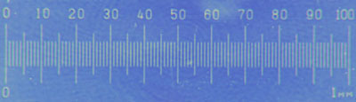
Metric graticule in polarised light
On some microscopes, a scale bar is superimposed on one of the eyepieces, which can be used to further improve the accuracy of measuring feature sizes. The scale bar can be calibrated by observing either a graticule or a ruler at a low magnification. For example, if 1 division is equivalent to 20 mm with a ×5 magnification lens, each division is equivalent to 2 mm with a ×50 magnification lens. By measuring a feature using the scale in the eyepiece, the actual size of the feature can be calculated by knowing the width of the divisions in the eyepiece. The scale bar on the eyepiece is particularly useful because it can be rotated, and so both widths and lengths can be measured without rotating the specimen.