
2.1.10: Exercises


- Last updated
- Jun 6, 2021
- Save as PDF

( \newcommand{\kernel}{\mathrm{null}\,}\)
Analysis
1. For the circuit of Figure 3.10.1 , determine the circulating current.
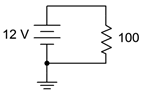
Figure 3.10.1
Answer 1
- 120mA
2. For the circuit of Figure 3.10.2 , determine the circulating current.
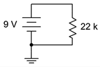
Figure 3.10.2
3. For the circuit of Figure 3.10.1 , determine the power dissipated in the resistor.
Answer 3
- 1.44W
4. For the circuit of Figure 3.10.2 , determine the power dissipated in the resistor.
5. Determine the voltage at the open terminals of Figure 3.10.3 .
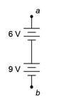
Figure 3.10.3
Answer 5
- 15 V
6. Determine the voltage at the open terminals of Figure 3.10.4 .
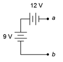
Figure 3.10.4
7. Determine the voltage at the open terminals of Figure 3.10.5 .
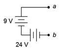
Figure 3.10.5
Answer 7
- 33 V
8. Determine the equivalent resistance of circuit shown in Figure 3.10.6 .
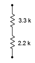
Figure 3.10.6
9. Determine the equivalent resistance of circuit shown in Figure 3.10.7 .
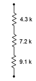
Figure 3.10.7
Answer 9
- 2.6k\Omega
10. Determine the equivalent resistance of circuit shown in Figure 3.10.8 .
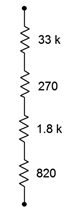
Figure 3.10.8
11. For the circuit of Figure 3.10.9 , determine the circulating current.
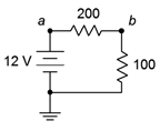
Figure 3.10.9
Answer 11
- 40 mA
12. For the circuit of Figure 3.10.9 , determine the voltages across each resistor and find V_{ab}.
13. Given the circuit of Figure 3.10.9 , determine the power dissipated by each resistor and the power delivered by the source.
Answer 13
- 320mW (200\Omega)
- 160mW (100\Omega)
- 480mW (source)
14. For the circuit of Figure 3.10.10 , determine the circulating current.
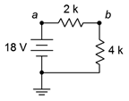
Figure 3.10.10
15. Given the circuit of Figure 3.10.10 , determine the voltages across each resistor and find V_{ba}.
Answer 15
- 6V(2k\Omega)
- 12V(4k\Omega)
- -6V (V_{ba})
16. For the circuit of Figure 3.10.10 , determine the power dissipated by each resistor and the power delivered by the source.
17. For the circuit of Figure 3.10.11 , determine the circulating current.
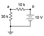
Figure 3.10.11
Answer 17
- 0.25 A
18. For the circuit of Figure 3.10.11 , determine the voltages across each resistor and find V_a.
19. For the circuit of Figure 3.10.12 , determine the circulating current and indicate all voltage polarities.
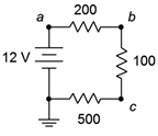
Figure 3.10.12
Answer 19
- I = 15mA
- V_{ab}: + on left, - on right
- V_{bc}: + on top, - on bottom
- V_{c}: + on right, - on left
- V_{src}: + on top, - on bottom
20. Given the circuit of Figure 3.10.12 , determine the voltages across each resistor and find V_b, V_{bc}, and V_{ca}.
21. For the circuit of Figure 3.10.12 , determine the power delivered by the source.
Answer 21
- P = 180mW
22. For the circuit of Figure 3.10.13 , determine the circulating current and indicate all voltage polarities.
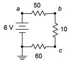
Figure 3.10.13
23. Given the circuit of Figure 3.10.13 , determine the voltages across each resistor and find V_c, V_{ac}, and V_a.
Answer 23
- V_{50}=2.5V
- V_{10}=0.5V
- V_{60}=3V
- V_{c}=3V
- V_{ac}=3V
- V_{a}=6V
24. For the circuit of Figure 3.10.13 , determine the power dissipated by the 10 \Omega resistor.
25. For the circuit of Figure 3.10.14 , determine the circulating current and indicate all voltage polarities.
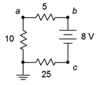
Figure 3.10.14
Answer 25
- I = 200mA
- V_{5}: + on right, - on left
- V_{10}: + on top, - on bottom
- V_{25}: + on left, - on right
- V_{src}: + on top, - on bottom
26. For the circuit of Figure 3.10.14 , determine the voltages across each resistor and find V_b, V_c, and V_{ca}.
27. Referring to the circuit of 3.10.15 , determine the voltages across each resistor and find V_b, V_c, and V_{ac}.
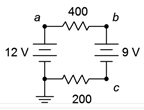
Figure 3.10.15
Answer 27
- V_{400}=2V
- V_{200}=1V
- V_{b}=10V
- V_{c}=1V
- V_{ac}=11V
28. Referring to the circuit of Figure 3.10.15 , determine the circulating current and indicate all voltage polarities.
29. Given the circuit of 3.10.16 , determine the voltages across each resistor and find V_b, V_c, and V_{ac}.
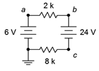
Figure 3.10.16
Answer 29
- V_{2k}=3.6V
- V_{8k}=14.4V
- V_{b}=9.6V
- V_{c}=-14.4V
- V_{ac}=20.4V
30. Referring to the circuit of Figure 3.10.16 , determine the circulating current and indicate all voltage polarities.
31. Given the circuit of 3.10.17 , determine the circulating current and indicate all voltage polarities.
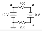
Figure 3.10.17
Answer 31
- I = 35mA
- V_{400}: + on left, - on right
- V_{200}: + on right, - on left
- V_{12Vsrc}: + on top, - on bottom
- V_{9Vsrc}: + on bottom, - on top
32. Referring to the circuit of Figure 3.10.17 , determine the voltages across each resistor and find V_b, V_c, and V_{ac}.
33. Given the circuit of 3.10.18 , determine the circulating current and indicate all voltage polarities.
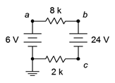
Figure 3.10.18
Answer 33
- I = 1.89mA
- V_{2k}: + on left, - on right
- V_{8k}: + on right, - on left
- V_{6Vsrc}: + on top, - on bottom
- V_{24Vsrc}: + on top, - on bottom
34. Referring to the circuit of Figure 3.10.18 , determine the voltages across each resistor and find V_b, V_c, and V_{ac}.
35. Using the voltage divider rule, determine the voltages V_b, V_c and V_{ac} for the circuit shown in Figure 3.10.19 .
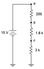
Figure 3.10.19
Answer 35
- V_{b} = 14.4V
- V_{c} = 9V
- V_{ac} = 6V
36. Using the voltage divider rule, determine the voltages V_b, V_c and V_{bd} for the circuit shown in Figure 3.10.20 .
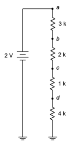
Figure 3.10.20
37. For the circuit of Figure 3.10.20 , determine V_b if the 4 k\Omega resistor is accidentally shorted. How does this compare to the original circuit?
Answer 37
- V_{b} = 1V. The 2V is now split across the three remaining resistors
38. For the circuit of Figure 3.10.20 , determine V_b if the 4 k\Omega resistor is accidentally opened. How does this compare to the original circuit?
39. Given the circuit shown in Figure 3.10.21 , find the voltage drop across the resistor.
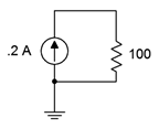
Figure 3.10.21
Answer 39
- 20V
40. Given the circuit shown in Figure 3.10.22 , find the voltage drops across the resistor.
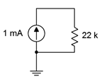
Figure 3.10.22
41. Find the voltage drops across the resistors in the circuit of Figure 3.10.23 .
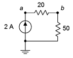
Figure 3.10.23
Answer 41
- V_{20} = 40V
- V_{20} = 100V
42. Find the voltage drops across the resistors in the circuit of Figure 3.10.24 .
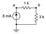
Figure 3.10.24
43. Find the voltage drops across the resistors in the circuit of Figure 3.10.25 .
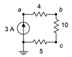
Figure 3.10.25
Answer 43
- V_{4} = 12V
- V_{10} = 30V
- V_{5} = 15V
44. Find the voltage drops across the resistors in the circuit of Figure 3.10.26 .
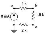
Figure 3.10.26
45. The circuit of Figure 3.10.27 uses a linear taper potentiometer. Determine V_b when the wiper arm is at position a, position b, and at the halfway point.
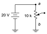
Figure 3.10.27
Answer 45
- V_{b} = 0V. This is true no matter where the wiper arm of the potentiometer is
46. What is the maximum current flowing through the potentiometer of Figure 3.10.27 ? At what position(s) does this occur?
Design
47. Redesign the circuit of Figure 3.10.1 using a new resistor such that the current from the 12 volt battery is 0.1 A.
Answer 47
- Change the 100 \Omega resistor to 120 \Omega
48. Redesign the circuit of Figure 3.10.2 using a new resistor such that the current from the 9 volt battery is 2 mA.
49. For the circuit of Figure 3.10.6 , find the value of a series voltage source that would generate 1 mA of current if it was connected across the terminals.
Answer 49
- 5.5V
50. For the circuit of Figure 3.10.8 , find the value of a series voltage source that would generate 1 mA of current if it was connected across the terminals.
51. Determine values for the resistors in Figure 3.10.28 such that R_1 is four times the size of R_2 and R_2 is three times the size of R3, with the total resistance equaling 8 k\Omega.
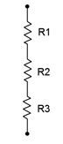
Figure 3.10.28
Answer 51
- R_{1} = 6k\Omega
- R_{2} = 1.5k\Omega
- R_{3} = 500\Omega
52. For the circuit shown in Figure 3.10.29 , determine values for R_1 and R_2 such that V_{ab} is 6 volts if E is a 9 volt battery and the total current draw is 20 mA.
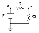
Figure 3.10.29
53. Consider the circuit shown in Figure 3.10.30 . If all resistors have the same value, determine that value if E, a 24 volt source, generates a total power of 10 watts.

Figure 3.10.30
Answer 53
- 19.2\Omega
54. For the circuit shown in Figure 3.10.31 , determine values for R_1 and R_2 such that V_{ab} is 6 volts if I is a 2 mA source and the total voltage drop is 24 volts.
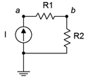
Figure 3.10.31
55. Consider the circuit of Figure 3.10.20 . Is it possible to add a fifth resistor such that the circulating current is 0.1 mA? If so, what is that resistor value?
Answer 55
- Yes, 10 k\Omega
56. Consider the circuit of Figure 3.10.20 . Is it possible to add a fifth resistor such that the circulating current is 2 mA? If so, what is that resistor value?
Challenge
57. Assume that two AA cells, E_1 and E_2, rated at 900 mAh each are used to drive a 2 watt lamp as shown in Figure 3.10.32 . Determine the expected life of the batteries.
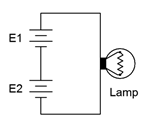
Figure 3.10.32
58. Given the circuit of Figure 3.10.33 , determine the required values of E, R_1, R_2 and R_3 if there is one volt across R_3, the total current draw is 10 mA, the voltage across R_1 is twice the size of voltage across R_2 and the power dissipation in R_2 is 100 mW.
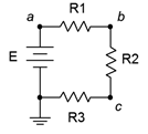
Figure 3.10.33
59. Given the circuit of Figure 3.10.33 , determine the required source voltage if R_1 is 1 k\Omega, R_2 is 1 k\Omega, the power dissipation in R_1 is 4 mW and the power dissipation in R_3 is 2 mW.
60. Given the circuit of Figure 3.10.34 , determine V_c, V_{db} and V_{ce}.
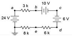
Figure 3.10.34
61. Given the circuit of Figure 3.10.34 , determine V_{ac}, V_{eb} and V_d.
62. Refer to the circuit of Figure 3.10.20 . Assuming each resistor has a 10% tolerance, determine the maximum and minimum values for V_c.
Simulation
63. Simulate the solution of design problem 43 and determine if the values produce the required results.
64. Perform a DC simulation on the circuit of Figure 3.10.13 and find all of the node voltages along with the circulating current.
65. Perform a DC simulation on the circuit of Figure 3.10.14 and find all of the node voltages along with the circulating current.
66. Perform a DC simulation on the circuit of Figure 3.10.26 and find all of the node voltages.
67. Perform a DC simulation on the circuit of Problem 34 and find all of the node voltages.
68. Perform a DC simulation on the circuit of Problem 36 and find all of the node voltages.
69. Simulate the solution of Challenge problem 58 and determine if the values produce the required results.
70. Simulate the circuit of Figure 3.10.34 (Challenge problems 60 and 61) and determine if the node voltages produced match the expected results.
71. Perform a Monte Carlo simulation on the circuit of Figure 3.10.19 . Set each resistor to 5% tolerance and run at least ten variations for V_b to determine a typical spread of values.
Source: www.xkcd.com