Keeping in mind that the voltage across each element in a parallel configuration is constant, Ohm's law dictates that currents divide among parallel resistors in proportion to their conductance (i.e., in inverse proportion to their resistance). As a consequence, Ohm's law, Kirchhoff's current law, the current divider rule and parallel component combinations are the tools we will use to solve general parallel circuit problems. There are multiple techniques for analyzing these circuits:
A simple parallel network is shown in Figure 4.5.1
. Determine the current through each resistor as well as the total current exiting the voltage source.

Figure 4.5.1
: Circuit for Example 4.5.1
.
The most direct solution is to use Ohm's law to determine each of the resistor branch currents. KCL can then be used to determine the current flowing from the source. Recalling the voltage is the same across parallel branches:
\[I_{600} = \frac{E}{R_1} \nonumber \]
\[I_{600} = \frac{12 V}{600 \Omega} \nonumber \]
\[I_{600} = 20 mA \nonumber \]
\[I_{400} = \frac{E}{R_2} \nonumber \]
\[I_{400} = \frac{12 V}{400 \Omega} \nonumber \]
\[I_{400} = 30 mA \nonumber \]
KCL dictates that the entering current must equal the sum of the exiting currents, or 50 mA.
An alternate technique would be to determine the parallel resistance and divide this into the source voltage to determine the exiting source current.
\[R_{Parallel} = \frac{R_1 R_2}{R_1+R_2} \nonumber \]
\[R_{Parallel} = \frac{400 \Omega 600 \Omega}{400 \Omega +600 \Omega} \nonumber \]
\[R_{Parallel} = 240 \Omega \nonumber \]
\[I_{Total} = \frac{E}{R_{Parallel}} \nonumber \]
\[I_{Total} = \frac{12 V}{240 \Omega} \nonumber \]
\[I_{Total} = 50 mA \nonumber \]
Now CDR can be used to find the currents through the two resistors.
\[I_{R1}= I_{Total} \frac{R_2}{R_1+R_2} \nonumber \]
\[I_{400} = 50mA \frac{600 \Omega}{ 400 \Omega +600 \Omega} \nonumber \]
\[I_{400} = 30 mA \nonumber \]
\[I_{R2} = I_{Total} \frac{R_1}{R_1+R_2} \nonumber \]
\[I_{600} = 50 mA \frac{400 \Omega}{400 \Omega +600 \Omega} \nonumber \]
\[I_{600} = 20 mA \nonumber \]
The voltage polarities and current directions are illustrated in Figure 4.5.2
. The voltage polarity is + to − from top to bottom, as set by the voltage source. With these polarities, the currents through the two resistors must be flowing from top to bottom and the current from the source is flowing right, from the positive terminal. At the top node, entering current is in red with exiting current in blue.
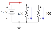
Figure 4.5.2
: Polarities and directions for Example 4.5.1
.
Computer Simulation
The circuit of Example 4.5.1
is entered into a simulator as shown in Figure 4.5.3
. In this example, virtual instruments are used. Three ammeters are inserted in line to measure the current exiting the voltage source as well as the currents flowing through the two resistors. The polarities of the ammeters are set to match those illustrated in Figure 4.5.2
. As a consequence, we expect to see all positive currents.
The result is pretty much as expected. The current through the 600 \( \Omega \) resistor is precisely 20 mA and the source current is precisely the sum of the two resistor currents. The only wrinkle is that the current through the 400 \( \Omega \) resistor is very slightly less than expected, 29.999 mA versus 30 mA calculated. This is due to meter loading effects. In Chapter 3 we saw that ammeters present a very low internal resistance, but this cannot always be ignored, especially when measuring in series with resistors having very small values. This slight increase in resistance forces a slight decrease in current due to Ohm's law.
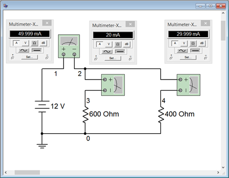
Figure 4.5.3
: The circuit of Example 4.5.1
in a simulator.
It turns out that a similar situation exists for voltmeters. Ideally, voltmeters present a very high internal resistance which, when placed across a resistor, has minimal impact. This effect cannot always be ignored, especially when measuring across resistors having large values, as the current divider rule will come into play. Fortunately, the internal resistance of many virtual instruments is adjustable and can be set to extreme values to minimize any impact on measurements. In the world of physical instruments this is not possible so the internal resistance of any real world meter is something that must always be kept in mind.
A parallel network is shown in Figure 4.5.4
. Determine the current through each resistor.
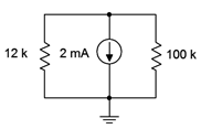
Figure 4.5.4
: Circuit for Example 4.5.2
.
The current divider rule can be used to find the currents through the two resistors. At the bottom node (ground) the total entering current is 2 mA.
\[I_{R1} = I_{Total} \frac{R_2}{R_1+R_2} \nonumber \]
\[I_{12k} = 2mA \frac{100 k \Omega}{12 k \Omega +100 k \Omega} \nonumber \]
\[I_{12k} \approx 1.7857 mA \nonumber \]
The current through the 100 k\( \Omega \) can be found via KCL as follows:
\[I_{R2} = I_{Total} − I_{R1} \nonumber \]
\[I_{100k} = 2 mA −1.7857 mA \nonumber \]
\[I_{100k} \approx 0.2143 mA \nonumber \]
The polarities and directions are shown in Figure 4.5.5
. Note that the currents are flowing up through the resistors producing voltage drops of + to − from ground up to the top. This means that the voltage of the top node is negative with respect to ground.
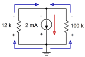
Figure 4.5.5
: Polarities and directions for Example 4.5.2
.
Computer Simulation
In order to get a better handle on the idea of meter loading, the circuit shown in Example 4.5.2
is entered into a simulator. This is shown in Figure 4.5.6
with the simulation using virtual instruments. Using Ohm's law, the voltage drop across the system should be 100 k\( \Omega \) times its current, or approximately 21.4286 volts if we carry the digits out a little further.
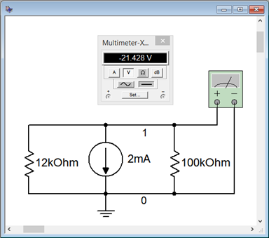
Figure 4.5.6
: The circuit of Example 4.5.2
in a simulator.
The virtual voltmeter has been set for an internal resistance of 1 G\( \Omega \). The results are nearly the same as those calculated previously. To test the impact of the voltmeter's internal resistance the simulation is run a second time with the internal resistance set to 1 M\( \Omega \), a value seen commonly in general purpose digital multimeters. The result is shown in Figure 4.5.7
. The voltage magnitude has dropped more than 200 mV, entirely due to meter loading.
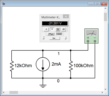
Figure 4.5.7
: Simulation repeated using a voltmeter internal resistance of 1 M\( \Omega \).
Depending on component values, the results could be much worse or hardly noticeable at all. As a general rule, make sure the voltmeter's internal resistance is at least 10 times (and preferably, 100 times) larger than any resistance it is placed across in order to avoid loading errors caused by unwanted current division. In the case of an ammeter, its internal resistance should be at least 10 times (and preferably, 100 times) smaller than any resistance with which it is placed in series.
A parallel network is shown in Figure 4.5.8
. Determine the current through the 200 \( \Omega \) resistor.
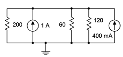
Figure 4.5.8
: Circuit for Example 4.5.3
.
The first step is to simplify the circuit. The two current sources aid each other as they both feed current into the top node. Thus they are equivalent to a single 1.4 amp current source with the same direction. Further, the 60 \( \Omega \) and 120 \( \Omega \) resistors are in parallel and can be treated as a single unit. Note this is a 2:1 ratio, and thus the result will be 2/3rds of 60 \( \Omega \), or 40 \( \Omega \). The basic product-sum rule or conductance formula could also be used.
We have simplified the circuit down to a single 1.4 amp source feeding a 200 \( \Omega \) resistor in parallel with a 40 \( \Omega \) resistor. The current divider rule can be used to find the current through the 200 \( \Omega \) resistor as follows:
\[I_{R1} = I_{Total} \frac{R_2}{R_1+R_2} \nonumber \]
\[I_{200} = 1.4 A \frac{40 \Omega}{200 \Omega + 40 \Omega} \nonumber \]
\[I_{200} \approx 233.33 mA \nonumber \]
As a crosscheck, Ohm's law indicates the system voltage must be 200 \( \Omega \) times 233.33 mA, or approximately 46.667 volts. Via Ohm's law, the current through the 60 \( \Omega \) must be 46.667 volts divided by 60 \( \Omega \), or approximately 777.78 mA. Similarly, the current through the 120 \( \Omega \) can be determined to be approximately 388.89 mA. Via KCL, these three currents should add up to the total supplied current of 1.4 amps, which they do.
An alternate solution path would be to find the equivalent of the three parallel resistors, or \(200 || 60 || 120\), which is 33.333 \( \Omega \). This is fed by the combined sources yielding 1.4 amps. Ohm's law is then used to find the system voltage of approximately 46.667 volts (1.4 amps times 33.333 \( \Omega \)). From there Ohm's law is used again to find the current flowing through the 200 \( \Omega \) (46.667 volts divided by 200 \( \Omega \), or approximately 233.33 mA).
Let's continue with the prior example, this time with a design twist.
Using the circuit of Figure 4.5.8
, determine the value of an additional fourth parallel resistor such that the system voltage will drop to 42 volts.
The total source current in this circuit is fixed at 1.4 amps. If the resistance it feeds is reduced, then by Ohm's law, the system voltage must also be reduced. One way to solve this problem is to first determine the required parallel equivalent resistance. Then the conductances of the three known resistors can be subtracted out, leaving the conductance of the new resistor, from which we determine its resistance.
\[R_{Parallel} = \frac{V}{I} \nonumber \]
\[R_{Parallel} = \frac{42 V}{1.4A} \nonumber \]
\[R_{Parallel} = 30 \Omega \nonumber \]
\[G_4 = G_{Parallel} − G_1 − G_2 − G_3 \nonumber \]
\[G_4 = \frac{1}{30 \Omega} − \frac{1}{200 \Omega} − \frac{1}{60 \Omega} − \frac{1}{120 \Omega} \nonumber \]
\[G_4 \approx 3.333mS \nonumber \]
And finally, \(R_4 = 1/G_4\), thus \(R_4 = 300 \Omega \).
The smaller the value of this fourth resistor, the more current it will siphon off from the other three resistors, thus reducing the system voltage further.
Time for an example involving power.
A parallel network is shown in Figure 4.5.9
. Determine the total power dissipated by the four resistors.
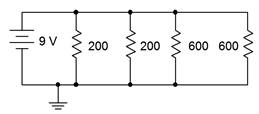
Figure 4.5.9
: Circuit for Example 4.5.5
.
While the powers for each resistor can be calculated individually and then added, it is worthwhile to note that the total power dissipated must be equal to the power generated. The power generated by the battery is dictated by power law, in other words, the battery voltage times its output current. To find this current, we can determine the effective resistance and then apply Ohm's law.
The total resistance can be found directly by using the conductance formula, however, the values can be divided into convenient pairs first. The pair of 200 \( \Omega \) resistors is equivalent to a single 100 \( \Omega \). Similarly, the two 600 \( \Omega \) resistors are equivalent to a single 300 \( \Omega \). Product-sum rule may be used next or \(100 || 300\) can be determined using the ratio rule. This is a 3:1 ratio, so the result will 3/4ths of the smaller resistor, or 75 \( \Omega \).
\[I_{Total} = \frac{E}{R_{Total}} \nonumber \]
\[I_{Total} = \frac{9 V}{75 \Omega} \nonumber \]
\[I_{Total} = 120 mA \nonumber \]
\[P = E \times I \nonumber \]
\[P = 9V \times 120 mA \nonumber \]
\[P = 1.08 W \nonumber \]
Slightly quicker, we could also use the following approach:
\[P = \frac{E^2}{R} \nonumber \]
\[P = \frac{(9 V)^2}{75 \Omega} \nonumber \]
\[P = 1.08 W \nonumber \]


