
2.3.8: Exercises
- Page ID
- 52897

\( \newcommand{\vecs}[1]{\overset { \scriptstyle \rightharpoonup} {\mathbf{#1}} } \)
\( \newcommand{\vecd}[1]{\overset{-\!-\!\rightharpoonup}{\vphantom{a}\smash {#1}}} \)
\( \newcommand{\id}{\mathrm{id}}\) \( \newcommand{\Span}{\mathrm{span}}\)
( \newcommand{\kernel}{\mathrm{null}\,}\) \( \newcommand{\range}{\mathrm{range}\,}\)
\( \newcommand{\RealPart}{\mathrm{Re}}\) \( \newcommand{\ImaginaryPart}{\mathrm{Im}}\)
\( \newcommand{\Argument}{\mathrm{Arg}}\) \( \newcommand{\norm}[1]{\| #1 \|}\)
\( \newcommand{\inner}[2]{\langle #1, #2 \rangle}\)
\( \newcommand{\Span}{\mathrm{span}}\)
\( \newcommand{\id}{\mathrm{id}}\)
\( \newcommand{\Span}{\mathrm{span}}\)
\( \newcommand{\kernel}{\mathrm{null}\,}\)
\( \newcommand{\range}{\mathrm{range}\,}\)
\( \newcommand{\RealPart}{\mathrm{Re}}\)
\( \newcommand{\ImaginaryPart}{\mathrm{Im}}\)
\( \newcommand{\Argument}{\mathrm{Arg}}\)
\( \newcommand{\norm}[1]{\| #1 \|}\)
\( \newcommand{\inner}[2]{\langle #1, #2 \rangle}\)
\( \newcommand{\Span}{\mathrm{span}}\) \( \newcommand{\AA}{\unicode[.8,0]{x212B}}\)
\( \newcommand{\vectorA}[1]{\vec{#1}} % arrow\)
\( \newcommand{\vectorAt}[1]{\vec{\text{#1}}} % arrow\)
\( \newcommand{\vectorB}[1]{\overset { \scriptstyle \rightharpoonup} {\mathbf{#1}} } \)
\( \newcommand{\vectorC}[1]{\textbf{#1}} \)
\( \newcommand{\vectorD}[1]{\overrightarrow{#1}} \)
\( \newcommand{\vectorDt}[1]{\overrightarrow{\text{#1}}} \)
\( \newcommand{\vectE}[1]{\overset{-\!-\!\rightharpoonup}{\vphantom{a}\smash{\mathbf {#1}}}} \)
\( \newcommand{\vecs}[1]{\overset { \scriptstyle \rightharpoonup} {\mathbf{#1}} } \)
\( \newcommand{\vecd}[1]{\overset{-\!-\!\rightharpoonup}{\vphantom{a}\smash {#1}}} \)
\(\newcommand{\avec}{\mathbf a}\) \(\newcommand{\bvec}{\mathbf b}\) \(\newcommand{\cvec}{\mathbf c}\) \(\newcommand{\dvec}{\mathbf d}\) \(\newcommand{\dtil}{\widetilde{\mathbf d}}\) \(\newcommand{\evec}{\mathbf e}\) \(\newcommand{\fvec}{\mathbf f}\) \(\newcommand{\nvec}{\mathbf n}\) \(\newcommand{\pvec}{\mathbf p}\) \(\newcommand{\qvec}{\mathbf q}\) \(\newcommand{\svec}{\mathbf s}\) \(\newcommand{\tvec}{\mathbf t}\) \(\newcommand{\uvec}{\mathbf u}\) \(\newcommand{\vvec}{\mathbf v}\) \(\newcommand{\wvec}{\mathbf w}\) \(\newcommand{\xvec}{\mathbf x}\) \(\newcommand{\yvec}{\mathbf y}\) \(\newcommand{\zvec}{\mathbf z}\) \(\newcommand{\rvec}{\mathbf r}\) \(\newcommand{\mvec}{\mathbf m}\) \(\newcommand{\zerovec}{\mathbf 0}\) \(\newcommand{\onevec}{\mathbf 1}\) \(\newcommand{\real}{\mathbb R}\) \(\newcommand{\twovec}[2]{\left[\begin{array}{r}#1 \\ #2 \end{array}\right]}\) \(\newcommand{\ctwovec}[2]{\left[\begin{array}{c}#1 \\ #2 \end{array}\right]}\) \(\newcommand{\threevec}[3]{\left[\begin{array}{r}#1 \\ #2 \\ #3 \end{array}\right]}\) \(\newcommand{\cthreevec}[3]{\left[\begin{array}{c}#1 \\ #2 \\ #3 \end{array}\right]}\) \(\newcommand{\fourvec}[4]{\left[\begin{array}{r}#1 \\ #2 \\ #3 \\ #4 \end{array}\right]}\) \(\newcommand{\cfourvec}[4]{\left[\begin{array}{c}#1 \\ #2 \\ #3 \\ #4 \end{array}\right]}\) \(\newcommand{\fivevec}[5]{\left[\begin{array}{r}#1 \\ #2 \\ #3 \\ #4 \\ #5 \\ \end{array}\right]}\) \(\newcommand{\cfivevec}[5]{\left[\begin{array}{c}#1 \\ #2 \\ #3 \\ #4 \\ #5 \\ \end{array}\right]}\) \(\newcommand{\mattwo}[4]{\left[\begin{array}{rr}#1 \amp #2 \\ #3 \amp #4 \\ \end{array}\right]}\) \(\newcommand{\laspan}[1]{\text{Span}\{#1\}}\) \(\newcommand{\bcal}{\cal B}\) \(\newcommand{\ccal}{\cal C}\) \(\newcommand{\scal}{\cal S}\) \(\newcommand{\wcal}{\cal W}\) \(\newcommand{\ecal}{\cal E}\) \(\newcommand{\coords}[2]{\left\{#1\right\}_{#2}}\) \(\newcommand{\gray}[1]{\color{gray}{#1}}\) \(\newcommand{\lgray}[1]{\color{lightgray}{#1}}\) \(\newcommand{\rank}{\operatorname{rank}}\) \(\newcommand{\row}{\text{Row}}\) \(\newcommand{\col}{\text{Col}}\) \(\renewcommand{\row}{\text{Row}}\) \(\newcommand{\nul}{\text{Nul}}\) \(\newcommand{\var}{\text{Var}}\) \(\newcommand{\corr}{\text{corr}}\) \(\newcommand{\len}[1]{\left|#1\right|}\) \(\newcommand{\bbar}{\overline{\bvec}}\) \(\newcommand{\bhat}{\widehat{\bvec}}\) \(\newcommand{\bperp}{\bvec^\perp}\) \(\newcommand{\xhat}{\widehat{\xvec}}\) \(\newcommand{\vhat}{\widehat{\vvec}}\) \(\newcommand{\uhat}{\widehat{\uvec}}\) \(\newcommand{\what}{\widehat{\wvec}}\) \(\newcommand{\Sighat}{\widehat{\Sigma}}\) \(\newcommand{\lt}{<}\) \(\newcommand{\gt}{>}\) \(\newcommand{\amp}{&}\) \(\definecolor{fillinmathshade}{gray}{0.9}\)Analysis
1. Determine the effective resistance of the network shown in Figure 4.8.1 .
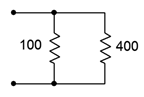
Figure 4.8.1
Answer 1
- 80 \(\Omega\)
2. Determine the effective resistance of the network shown in Figure 4.8.2 .
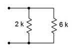
Figure 4.8.2
3. Determine the effective resistance of the network shown in Figure 4.8.3 .
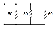
Figure 4.8.3
Answer 3
- 14.3 \(\Omega\)
4. Find the effective source current of the network shown in Figure 4.8.4 .
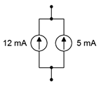
Figure 4.8.4
5. Determine the effective source current of the network shown in Figure 4.8.5 .
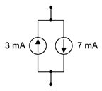
Figure 4.8.5
Answer 5
- 4mA, down
6. Find the source and resistor currents for the circuit of Figure 4.8.6 .
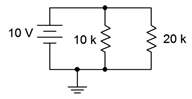
Figure 4.8.6
7. Determine the source and resistor currents for the circuit of Figure 4.8.7 .
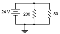
Figure 4.8.7
Answer 7
- \(I_{200} = 120mA\)
- \(I_{50} = 480mA\)
- \(I_{src} = 600mA\)
8. Find the source and resistor currents for the circuit of Figure 4.8.8 .
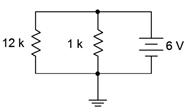
Figure 4.8.8
9. For the circuit of Figure 4.8.9 , determine the source and resistor currents.
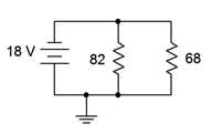
Figure 4.8.9
Answer 9
- \(I_{82} = 219.5mA\)
- \(I_{69} = 264.7mA\)
- \(I_{src} = 484.2mA\)
10. Determine the current through each resistor in the circuit of Figure 4.8.10 . Also determine the total power generated by the source.
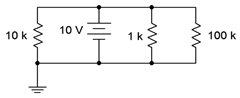
Figure 4.8.10
11. Consider the circuit shown in Figure 4.8.10 . Assume that the 100 k\(\Omega\) is replaced with another resistor ten times as large. Will this have a major impact on the current exiting source? Why/why not?
Answer 11
- No. It is already the smallest current by an order of magnitude, and this makes it smaller
12. Consider the circuit shown in Figure 4.8.10 . Assume that the 1 k\(\Omega\) is replaced with another resistor ten times smaller. Will this have a major impact on the current exiting source? Why/why not?
13. Find the current through each resistor in the circuit of Figure 4.8.11 .
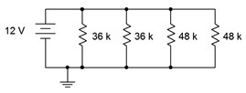
Figure 4.8.11
Answer 13
- \(I_{36k} = 333.3uA\)
- \(I_{48k} = 250uA\)
14. Determine the current through each resistor in the circuit of Figure 4.8.12 . Also determine the total current exiting by the source.
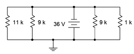
Figure 4.8.12
15. Determine the current through each resistor in the circuit of Figure 4.8.13 .
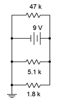
Figure 4.8.13
Answer 15
- \(I_{47k} = 0.1915mA\)
- \(I_{5.1k} = 1.765mA\)
- \(I_{1.8k} = 5mA\)
16. For the circuit shown in Figure 4.8.14 , determine the current through each resistor and the source voltage.
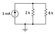
Figure 4.8.14
17. For the circuit shown in Figure 4.8.15 , determine the current through each resistor and the source voltage.
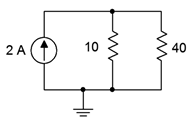
Figure 4.8.15
Answer 17
- \(I_{10} = 1.6A\)
- \(I_{40} = 0.4mA\)
- \(V_{src} = 16V\)
18. For the circuit shown in Figure 4.8.16 , determine the current through each resistor and the source voltage.
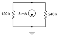
Figure 4.8.16
19. For the circuit shown in Figure 4.8.17 , determine the current through each resistor and the source voltage.
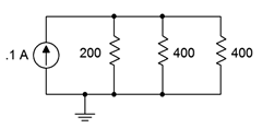
Figure 4.8.17
Answer 19
- \(I_{200} = 50mA\)
- \(I_{400} = 25mA\)
- \(V_{src} = 10 V\)
20. For the circuit shown in Figure 4.8.18 , determine the current through each resistor and the source voltage.
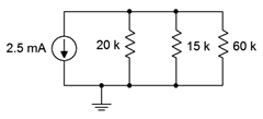
Figure 4.8.18
21. For the circuit shown in Figure 4.8.19 , determine the current through each resistor and the source voltage.
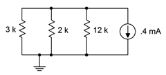
Figure 4.8.19
Answer 21
- \(I_{3k} = 145.5uA\)
- \(I_{2k} = 218.2uA\)
- \(I_{12k} = 28.57uA\)
- \(V_{src} = 0.4364V\)
22. For the circuit shown in Figure 4.8.20 , determine the current through each resistor and the source voltage.
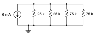
Figure 4.8.20
23. Referring to the circuit of Figure 4.8.20 , determine the resistor currents if the right-most 75 k\(\Omega\) resistor is accidentally opened (i.e., unconnected). How do these results compare to those of problem 22?
Answer 23
- \(I_{25k} = 2.571mA\)
- \(I_{75k} = 0.8571mA\)
- Currents will be higher in the 25k resistors because there is one fewer path for current to go
24. Referring to the circuit of Figure 4.8.20 , determine the resistor currents if the right-most 75 k\(\Omega\) resistor is accidentally shorted. How do these results compare to those of problems 22 and 23?
25. For the circuit shown in Figure 4.8.21 , determine the current through each resistor and the source voltage.
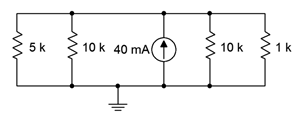
Figure 4.8.21
Answer 25
- \(I_{5k} = 15.714mA\)
- \(I_{10k} = 2.857mA\)
- \(I_{1k} = 28.57mA\)
- \(V_{src} = 28.57V\)
26. Given the circuit of Figure 4.8.22 , find the currents through the two resistors.
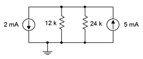
Figure 4.8.22
27. If the 5 mA current source shown in Figure 4.8.22 is accidentally wired in upside down, does the voltage across the 12 k \(\Omega\) resistor become more positive or more negative with respect to ground?
Answer 27
- The voltage is larger, but now negative, so it becomes more negative
28. Given the circuit of Figure 4.8.23 , find the voltages across the three resistors.
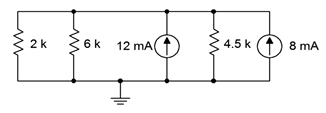
Figure 4.8.23
29. Find the currents through the three resistors in Figure 4.8.23 .
Answer 29
- \(I_{2k} = 11.25mA\)
- \(I_{6k} = 3.75mA\)
- \(I_{4.5k} = 5mA\)
Design
30. For the network shown in Figure 4.8.24 , determine a for values for \(R_1\) given that \(R_2\) is 12 k\(\Omega\) and the equivalent combination is 8 k\(\Omega\).
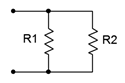
Figure 4.8.24
31. Add a third parallel resistor to the circuit of Figure 4.8.8 such that the source current is 10 mA.
Answer 31
- 1.714k\(\Omega\)
32. Add a fourth parallel resistor to the circuit of Figure 4.8.10 such that the source current is 20 mA.
33. Consider the circuit shown in Figure 4.8.14 . Determine a new value for the current source such that the source voltage equals 10 volts.
Answer 33
- 6.667mA
34. Consider the circuit shown in Figure 4.8.16 . Determine a new value for the current source such that the source voltage equals 20 volts.
35. Given the circuit of Figure 4.8.25 , if the source is 6 volts and \(R_1\) is 2 k\(\Omega\), what must be the value of \(R_2\) if the total current exiting the source is 10 mA?
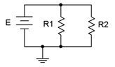
Figure 4.8.25
Answer 35
- 857\(\Omega\)
36. For the circuit shown in Figure 4.8.26 , determine values for resistors \(R_2\) and \(R_3\) such that the current through \(R_2\) is twice the current through \(R_1\) and the current through \(R_3\) is half the current through \(R_1\). The source is 6 volts and \(R_1\) is 2 k\(\Omega\).
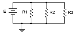
Figure 4.8.26
37. For the circuit shown in Figure 4.8.27 , determine values for resistors \(R_1\) and \(R_2\) such that the current through \(R_2\) is twice the current through \(R_1\). The source is 10 mA and \(R_1\) is 6 k\(\Omega\).
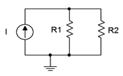
Figure 4.8.27
Answer 37
- 3k\(\Omega\)
Challenge
38. For the circuit shown in Figure 4.8.12 , determine a new value for the 11 k\(\Omega\) resistor such that the supply current is 50 mA.
39. For the circuit shown in Figure 4.8.14 , determine a new value for the 2 k\(\Omega\) resistor such that the voltage drop across the 6 k\(\Omega\) is 15 volts.
40. Consider the circuit shown in Figure 4.8.21 . If the current source was replaced with a voltage source, what value is needed so that the same currents flow through the resistors as in the original circuit?
41. For the network shown in Figure 4.8.24 , determine values for \(R_1\) and \(R_2\) such that \(R_2\) is twice the size of \(R_1\) and the equivalent combination is 6 k\(\Omega\).
42. Given the network of Figure 4.8.3 , is it possible to replace the 60 \(\Omega\) resistor with another value such that the equivalent combination of the three resistors is 25 \(\Omega\)? If so, what is that value?
43. Given the network of Figure 4.8.11 , is it possible to add a fifth parallel resistor such that the source current is 1 mA? If so, what is that value?
44. For the circuit shown in Figure 4.8.26 , determine values for the three resistors such that the current through \(R_1\) is twice the current through \(R_2\) and four times the current through \(R_3\). The source is 12 volts and should produce a total of 9 mA of current.
45. For the circuit shown in Figure 4.8.27 determine values for the two resistors such that the current through \(R_1\) is half the current through \(R_2\). The source is 24 mA and should produce a drop of 16 volts across \(R_1\).
46. Given three current sources with values of 1 mA, 2 mA and 7 mA; how would they need to be connected in order to deliver 4 volts across a 1 k\(\Omega\) load resistor?
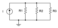
Figure 4.8.28
47. Consider the circuit of Figure 4.8.28 . Assume \(I\) is a 4 mA source. Using only 5% standard resistor values (see Appendix A), pick values for the three resistors such that the voltage across \(R_1\) is within 10% of 10 volts as long as the resistors are within tolerance.
Simulation
48. Verify the currents found in problem 11 via a DC simulation.
49. Verify the currents found in problem 15 via a DC simulation.
50. Verify the currents and voltages found in problem 17 via a DC simulation.
51. Verify the results found in problem 25 via a DC simulation.
52. Verify the results found in problem 27 via a DC simulation.
53. Perform a DC simulation on the design of problem 44 to verify its performance.
54. Perform a DC simulation on the design of problem 45 to verify its performance.
55. Perform a DC simulation on the design of problem 46 to verify its performance.
56. Perform a Monte Carlo or worst-case simulation on the design of problem 47 to verify its performance.