
5.3: Reflection Oscillator
- Page ID
- 113744

\( \newcommand{\vecs}[1]{\overset { \scriptstyle \rightharpoonup} {\mathbf{#1}} } \)
\( \newcommand{\vecd}[1]{\overset{-\!-\!\rightharpoonup}{\vphantom{a}\smash {#1}}} \)
\( \newcommand{\dsum}{\displaystyle\sum\limits} \)
\( \newcommand{\dint}{\displaystyle\int\limits} \)
\( \newcommand{\dlim}{\displaystyle\lim\limits} \)
\( \newcommand{\id}{\mathrm{id}}\) \( \newcommand{\Span}{\mathrm{span}}\)
( \newcommand{\kernel}{\mathrm{null}\,}\) \( \newcommand{\range}{\mathrm{range}\,}\)
\( \newcommand{\RealPart}{\mathrm{Re}}\) \( \newcommand{\ImaginaryPart}{\mathrm{Im}}\)
\( \newcommand{\Argument}{\mathrm{Arg}}\) \( \newcommand{\norm}[1]{\| #1 \|}\)
\( \newcommand{\inner}[2]{\langle #1, #2 \rangle}\)
\( \newcommand{\Span}{\mathrm{span}}\)
\( \newcommand{\id}{\mathrm{id}}\)
\( \newcommand{\Span}{\mathrm{span}}\)
\( \newcommand{\kernel}{\mathrm{null}\,}\)
\( \newcommand{\range}{\mathrm{range}\,}\)
\( \newcommand{\RealPart}{\mathrm{Re}}\)
\( \newcommand{\ImaginaryPart}{\mathrm{Im}}\)
\( \newcommand{\Argument}{\mathrm{Arg}}\)
\( \newcommand{\norm}[1]{\| #1 \|}\)
\( \newcommand{\inner}[2]{\langle #1, #2 \rangle}\)
\( \newcommand{\Span}{\mathrm{span}}\) \( \newcommand{\AA}{\unicode[.8,0]{x212B}}\)
\( \newcommand{\vectorA}[1]{\vec{#1}} % arrow\)
\( \newcommand{\vectorAt}[1]{\vec{\text{#1}}} % arrow\)
\( \newcommand{\vectorB}[1]{\overset { \scriptstyle \rightharpoonup} {\mathbf{#1}} } \)
\( \newcommand{\vectorC}[1]{\textbf{#1}} \)
\( \newcommand{\vectorD}[1]{\overrightarrow{#1}} \)
\( \newcommand{\vectorDt}[1]{\overrightarrow{\text{#1}}} \)
\( \newcommand{\vectE}[1]{\overset{-\!-\!\rightharpoonup}{\vphantom{a}\smash{\mathbf {#1}}}} \)
\( \newcommand{\vecs}[1]{\overset { \scriptstyle \rightharpoonup} {\mathbf{#1}} } \)
\(\newcommand{\longvect}{\overrightarrow}\)
\( \newcommand{\vecd}[1]{\overset{-\!-\!\rightharpoonup}{\vphantom{a}\smash {#1}}} \)
\(\newcommand{\avec}{\mathbf a}\) \(\newcommand{\bvec}{\mathbf b}\) \(\newcommand{\cvec}{\mathbf c}\) \(\newcommand{\dvec}{\mathbf d}\) \(\newcommand{\dtil}{\widetilde{\mathbf d}}\) \(\newcommand{\evec}{\mathbf e}\) \(\newcommand{\fvec}{\mathbf f}\) \(\newcommand{\nvec}{\mathbf n}\) \(\newcommand{\pvec}{\mathbf p}\) \(\newcommand{\qvec}{\mathbf q}\) \(\newcommand{\svec}{\mathbf s}\) \(\newcommand{\tvec}{\mathbf t}\) \(\newcommand{\uvec}{\mathbf u}\) \(\newcommand{\vvec}{\mathbf v}\) \(\newcommand{\wvec}{\mathbf w}\) \(\newcommand{\xvec}{\mathbf x}\) \(\newcommand{\yvec}{\mathbf y}\) \(\newcommand{\zvec}{\mathbf z}\) \(\newcommand{\rvec}{\mathbf r}\) \(\newcommand{\mvec}{\mathbf m}\) \(\newcommand{\zerovec}{\mathbf 0}\) \(\newcommand{\onevec}{\mathbf 1}\) \(\newcommand{\real}{\mathbb R}\) \(\newcommand{\twovec}[2]{\left[\begin{array}{r}#1 \\ #2 \end{array}\right]}\) \(\newcommand{\ctwovec}[2]{\left[\begin{array}{c}#1 \\ #2 \end{array}\right]}\) \(\newcommand{\threevec}[3]{\left[\begin{array}{r}#1 \\ #2 \\ #3 \end{array}\right]}\) \(\newcommand{\cthreevec}[3]{\left[\begin{array}{c}#1 \\ #2 \\ #3 \end{array}\right]}\) \(\newcommand{\fourvec}[4]{\left[\begin{array}{r}#1 \\ #2 \\ #3 \\ #4 \end{array}\right]}\) \(\newcommand{\cfourvec}[4]{\left[\begin{array}{c}#1 \\ #2 \\ #3 \\ #4 \end{array}\right]}\) \(\newcommand{\fivevec}[5]{\left[\begin{array}{r}#1 \\ #2 \\ #3 \\ #4 \\ #5 \\ \end{array}\right]}\) \(\newcommand{\cfivevec}[5]{\left[\begin{array}{c}#1 \\ #2 \\ #3 \\ #4 \\ #5 \\ \end{array}\right]}\) \(\newcommand{\mattwo}[4]{\left[\begin{array}{rr}#1 \amp #2 \\ #3 \amp #4 \\ \end{array}\right]}\) \(\newcommand{\laspan}[1]{\text{Span}\{#1\}}\) \(\newcommand{\bcal}{\cal B}\) \(\newcommand{\ccal}{\cal C}\) \(\newcommand{\scal}{\cal S}\) \(\newcommand{\wcal}{\cal W}\) \(\newcommand{\ecal}{\cal E}\) \(\newcommand{\coords}[2]{\left\{#1\right\}_{#2}}\) \(\newcommand{\gray}[1]{\color{gray}{#1}}\) \(\newcommand{\lgray}[1]{\color{lightgray}{#1}}\) \(\newcommand{\rank}{\operatorname{rank}}\) \(\newcommand{\row}{\text{Row}}\) \(\newcommand{\col}{\text{Col}}\) \(\renewcommand{\row}{\text{Row}}\) \(\newcommand{\nul}{\text{Nul}}\) \(\newcommand{\var}{\text{Var}}\) \(\newcommand{\corr}{\text{corr}}\) \(\newcommand{\len}[1]{\left|#1\right|}\) \(\newcommand{\bbar}{\overline{\bvec}}\) \(\newcommand{\bhat}{\widehat{\bvec}}\) \(\newcommand{\bperp}{\bvec^\perp}\) \(\newcommand{\xhat}{\widehat{\xvec}}\) \(\newcommand{\vhat}{\widehat{\vvec}}\) \(\newcommand{\uhat}{\widehat{\uvec}}\) \(\newcommand{\what}{\widehat{\wvec}}\) \(\newcommand{\Sighat}{\widehat{\Sigma}}\) \(\newcommand{\lt}{<}\) \(\newcommand{\gt}{>}\) \(\newcommand{\amp}{&}\) \(\definecolor{fillinmathshade}{gray}{0.9}\)Design of stable microwave oscillators traditionally uses the one-port oscillator stability criterion outlined by Kurokawa [11, 12]. Most two-port oscillators can be designed by casting them in the form of a one-port oscillator. In applying the condition, each of the networks—the active device, the resonator load, and the device termination—are characterized as one-ports.
Kurokawa Oscillation Condition
The oscillation condition for a stable reflection oscillator can be expressed in terms of the admittances of the resonator network, \(Y_{r} = G_{r} + \jmath B_{r}\), and of the active network, \(Y_{d} = G_{d} + \jmath B_{d}\), see Figure \(\PageIndex{1}\)(a). The Kurokawa oscillator condition establishes that for stable (single-frequency) oscillation [11]
\[\label{eq:1}\left.\left(\frac{\partial G_{d}}{\partial V}\frac{\partial B_{r}}{\partial\omega}-\frac{\partial B_{d}}{\partial V}\frac{\partial G_{r}}{\partial\omega}\right)\right|_{V=V_{0},\omega = \omega_{0}}>0 \]
where the subscript \(0\) refers to the operating point, \(r\) refers to the resonator, and \(d\) refers to the active device. The active device and resonator characteristics shown in Figures \(\PageIndex{1}\)(b and c) satisfy the Kurokawa condition. In Equation \(\eqref{eq:1}\) \(V_{0}\) is the amplitude of the oscillation at the interface of the active and resonator networks. If the condition in Equation \(\eqref{eq:1}\) is not met, then the oscillator may simultaneously oscillate at multiple frequencies. The Kurokawa oscillation condition must be met at all times which includes during start-up, including when bias is applied, of the oscillator.
With a fixed-frequency oscillator the resonator network is linear so \(G_{r}\) and \(B_{r}\) are independent of amplitude and \(G_{r}\) (by design) is independent of frequency. \(B_{r}\) varies with frequency. Ideally the active device has a frequency independent \(G_{d}\) and amplitude independent \(B_{d}\). Achieving this is a major design task. With these conditions \(\partial B_{d}/\partial V\approx 0\) and \(\partial G_{r}/\partial \omega_{0}\approx 0\) and the
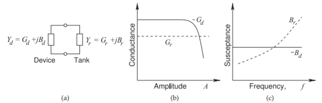
Figure \(\PageIndex{1}\): Reflection oscillator operation: (a) one-port oscillator; (b) as the amplitude of the oscillation increases, the magnitude of the device conductance, \(|G_{d}|\), decreases while the conductance of the tank circuit, \(G_{r}\), is constant; and (c) as the frequency of the oscillation increases, the susceptance of the tank circuit, \(B_{r}\), changes while, \(B_{d}\) (ideally) does not change.
Kurokawa condition in Equation \(\eqref{eq:1}\) simplifies to
\[\label{eq:2}\left.\left(\frac{\partial G_{d}}{\partial V}\frac{\partial B_{r}}{\partial\omega_{0}}\right)\right|_{V=V_{0},\omega =\omega_{0}}>0 \]
Thus design is greatly simplified for a fixed-frequency oscillator with a high-\(Q\) resonator.
Reflection Oscillator Design Approach
When a device with admittance \(Y_{d} = G_{d} + \jmath B_{d}\) is connected in shunt to a resonator of admittance \(Y_{r} = G_{r} +\jmath B_{r}\) (see Figure \(\PageIndex{1}\)(a)), the voltage amplitude \(A\) and radian frequency \(\omega\) of the resulting equilibrium oscillation are determined when \(−G_{d}(A) = G_{r}(\omega)\) and \(−B_{d}(A) = B_{r}(\omega )\). Here the assumption is that the device conductance only is a strong function of voltage amplitude, while the resonator admittance is a function only of angular frequency. This condition can be represented graphically by first denoting the locus of the negative of the device’s complex admittance as \(−Y_{d}(A) = −[G_{d}(A)+\jmath B_{d}(A)]\) (also referred to as the inverse device reflection coefficient, or \(1/\Gamma\) locus (sometimes referred to as the \(1/S\) locus)) and the locus of the resonator admittance as \(Y_{r}(\omega ) = G_{r}(\omega )+\jmath B_{r}(\omega )\). Then, for stable single-frequency oscillation, the intersection of these loci occurs at a single point (i.e., at a single amplitude and frequency combination).
In most oscillator design, the aim is to make the device admittance independent of frequency, and, of course, the admittance of the linear tank circuit is independent of the amplitude of the oscillating signal. These oscillation conditions are depicted in Figure \(\PageIndex{1}\)(b and c). In Figure \(\PageIndex{1}\)(b), as the amplitude of the oscillation increases, the magnitude of the device conductance, \(|G_{d}|\), decreases while the conductance of the tank circuit, \(G_{r}\), is constant. In Figure \(\PageIndex{1}\)(c), as the frequency of the oscillation increases, the susceptance of the tank circuit, \(B_{r}\), changes while \(B_{d}\) (ideally) is slow to change. The intersections define the amplitude and frequency of the oscillation.
If the device admittance is dependent on frequency, then it is difficult to avoid multiple intersections of the \(−Y_{d} (1/\Gamma_{d})\) and \(Y_{r} (\Gamma_{r})\) loci as viewed in the complex plane. The angle of intersection of the \(Y_{r}\) and \(−Y_{d}\) loci is an important indicator of stability relating to multiple oscillations, oscillator start-up problems, and excess noise [13]. Thus the appropriate angular intersection of these loci is critical. It is difficult to achieve all of the objectives in design unless \(Y_{d}\) is frequency independent.
Ideally, resonator design requires that \(Q\) be maximized so that \(G_{r}\approx 0\). This can be achieved with a fixed-frequency microwave oscillator as the resonator can be implemented with a capacitor and a transmission line segment both of which have very low loss. However the tunable capacitors in a VCO design are lossy and so the \(Q\) is not high. The two types of oscillators need a different design approach. Furthermore, for a VCO, voltage tuning of the resonator must satisfy the stability criteria, including a single point of intersection and appropriate angle of intersection, over the tuning range. With emphasis on these characteristics and since there are device capacitive parasitics, achieving a proper stable resonator-device interface can be troublesome. An alternative and equally viable approach to stability analysis of a broad class of oscillators, particularly for those using three-terminal devices, is application of the two-port criteria developed for amplifier stability assessment. However, the one-port design approach is preferred by microwave designers because the one-port connection is closer to the intended operation. The one-port assessment of oscillator stability is not unlike the Bode criteria applied to two-port feedback systems [14, 15]. However, unlike the two-port open-loop assessment of stability, the one-port characterization technique is conveniently aligned with the measurements that can be made by a VNA [16, 17]. As well, the nonlinear limiting effect of the active device is readily measured.
Summary
Microwave oscillator design invariably uses the reflection oscillator approach in which a one-port active device network is connected to a one-port resonator network. Design is complicated enough and it is necessary to simplify design and limit the design space. The procedure almost universally followed is to design for the characteristics shown in Figure \(\PageIndex{1}\). Design of a fixed-frequency oscillator is further simplified because the conductance of the resonator is almost zero.