
8.4: Momentum Conservation
- Page ID
- 746

\( \newcommand{\vecs}[1]{\overset { \scriptstyle \rightharpoonup} {\mathbf{#1}} } \)
\( \newcommand{\vecd}[1]{\overset{-\!-\!\rightharpoonup}{\vphantom{a}\smash {#1}}} \)
\( \newcommand{\dsum}{\displaystyle\sum\limits} \)
\( \newcommand{\dint}{\displaystyle\int\limits} \)
\( \newcommand{\dlim}{\displaystyle\lim\limits} \)
\( \newcommand{\id}{\mathrm{id}}\) \( \newcommand{\Span}{\mathrm{span}}\)
( \newcommand{\kernel}{\mathrm{null}\,}\) \( \newcommand{\range}{\mathrm{range}\,}\)
\( \newcommand{\RealPart}{\mathrm{Re}}\) \( \newcommand{\ImaginaryPart}{\mathrm{Im}}\)
\( \newcommand{\Argument}{\mathrm{Arg}}\) \( \newcommand{\norm}[1]{\| #1 \|}\)
\( \newcommand{\inner}[2]{\langle #1, #2 \rangle}\)
\( \newcommand{\Span}{\mathrm{span}}\)
\( \newcommand{\id}{\mathrm{id}}\)
\( \newcommand{\Span}{\mathrm{span}}\)
\( \newcommand{\kernel}{\mathrm{null}\,}\)
\( \newcommand{\range}{\mathrm{range}\,}\)
\( \newcommand{\RealPart}{\mathrm{Re}}\)
\( \newcommand{\ImaginaryPart}{\mathrm{Im}}\)
\( \newcommand{\Argument}{\mathrm{Arg}}\)
\( \newcommand{\norm}[1]{\| #1 \|}\)
\( \newcommand{\inner}[2]{\langle #1, #2 \rangle}\)
\( \newcommand{\Span}{\mathrm{span}}\) \( \newcommand{\AA}{\unicode[.8,0]{x212B}}\)
\( \newcommand{\vectorA}[1]{\vec{#1}} % arrow\)
\( \newcommand{\vectorAt}[1]{\vec{\text{#1}}} % arrow\)
\( \newcommand{\vectorB}[1]{\overset { \scriptstyle \rightharpoonup} {\mathbf{#1}} } \)
\( \newcommand{\vectorC}[1]{\textbf{#1}} \)
\( \newcommand{\vectorD}[1]{\overrightarrow{#1}} \)
\( \newcommand{\vectorDt}[1]{\overrightarrow{\text{#1}}} \)
\( \newcommand{\vectE}[1]{\overset{-\!-\!\rightharpoonup}{\vphantom{a}\smash{\mathbf {#1}}}} \)
\( \newcommand{\vecs}[1]{\overset { \scriptstyle \rightharpoonup} {\mathbf{#1}} } \)
\(\newcommand{\longvect}{\overrightarrow}\)
\( \newcommand{\vecd}[1]{\overset{-\!-\!\rightharpoonup}{\vphantom{a}\smash {#1}}} \)
\(\newcommand{\avec}{\mathbf a}\) \(\newcommand{\bvec}{\mathbf b}\) \(\newcommand{\cvec}{\mathbf c}\) \(\newcommand{\dvec}{\mathbf d}\) \(\newcommand{\dtil}{\widetilde{\mathbf d}}\) \(\newcommand{\evec}{\mathbf e}\) \(\newcommand{\fvec}{\mathbf f}\) \(\newcommand{\nvec}{\mathbf n}\) \(\newcommand{\pvec}{\mathbf p}\) \(\newcommand{\qvec}{\mathbf q}\) \(\newcommand{\svec}{\mathbf s}\) \(\newcommand{\tvec}{\mathbf t}\) \(\newcommand{\uvec}{\mathbf u}\) \(\newcommand{\vvec}{\mathbf v}\) \(\newcommand{\wvec}{\mathbf w}\) \(\newcommand{\xvec}{\mathbf x}\) \(\newcommand{\yvec}{\mathbf y}\) \(\newcommand{\zvec}{\mathbf z}\) \(\newcommand{\rvec}{\mathbf r}\) \(\newcommand{\mvec}{\mathbf m}\) \(\newcommand{\zerovec}{\mathbf 0}\) \(\newcommand{\onevec}{\mathbf 1}\) \(\newcommand{\real}{\mathbb R}\) \(\newcommand{\twovec}[2]{\left[\begin{array}{r}#1 \\ #2 \end{array}\right]}\) \(\newcommand{\ctwovec}[2]{\left[\begin{array}{c}#1 \\ #2 \end{array}\right]}\) \(\newcommand{\threevec}[3]{\left[\begin{array}{r}#1 \\ #2 \\ #3 \end{array}\right]}\) \(\newcommand{\cthreevec}[3]{\left[\begin{array}{c}#1 \\ #2 \\ #3 \end{array}\right]}\) \(\newcommand{\fourvec}[4]{\left[\begin{array}{r}#1 \\ #2 \\ #3 \\ #4 \end{array}\right]}\) \(\newcommand{\cfourvec}[4]{\left[\begin{array}{c}#1 \\ #2 \\ #3 \\ #4 \end{array}\right]}\) \(\newcommand{\fivevec}[5]{\left[\begin{array}{r}#1 \\ #2 \\ #3 \\ #4 \\ #5 \\ \end{array}\right]}\) \(\newcommand{\cfivevec}[5]{\left[\begin{array}{c}#1 \\ #2 \\ #3 \\ #4 \\ #5 \\ \end{array}\right]}\) \(\newcommand{\mattwo}[4]{\left[\begin{array}{rr}#1 \amp #2 \\ #3 \amp #4 \\ \end{array}\right]}\) \(\newcommand{\laspan}[1]{\text{Span}\{#1\}}\) \(\newcommand{\bcal}{\cal B}\) \(\newcommand{\ccal}{\cal C}\) \(\newcommand{\scal}{\cal S}\) \(\newcommand{\wcal}{\cal W}\) \(\newcommand{\ecal}{\cal E}\) \(\newcommand{\coords}[2]{\left\{#1\right\}_{#2}}\) \(\newcommand{\gray}[1]{\color{gray}{#1}}\) \(\newcommand{\lgray}[1]{\color{lightgray}{#1}}\) \(\newcommand{\rank}{\operatorname{rank}}\) \(\newcommand{\row}{\text{Row}}\) \(\newcommand{\col}{\text{Col}}\) \(\renewcommand{\row}{\text{Row}}\) \(\newcommand{\nul}{\text{Nul}}\) \(\newcommand{\var}{\text{Var}}\) \(\newcommand{\corr}{\text{corr}}\) \(\newcommand{\len}[1]{\left|#1\right|}\) \(\newcommand{\bbar}{\overline{\bvec}}\) \(\newcommand{\bhat}{\widehat{\bvec}}\) \(\newcommand{\bperp}{\bvec^\perp}\) \(\newcommand{\xhat}{\widehat{\xvec}}\) \(\newcommand{\vhat}{\widehat{\vvec}}\) \(\newcommand{\uhat}{\widehat{\uvec}}\) \(\newcommand{\what}{\widehat{\wvec}}\) \(\newcommand{\Sighat}{\widehat{\Sigma}}\) \(\newcommand{\lt}{<}\) \(\newcommand{\gt}{>}\) \(\newcommand{\amp}{&}\) \(\definecolor{fillinmathshade}{gray}{0.9}\)The relationship among the shear stress various components have to be established. The stress is a relationship between the force and area it is acting on or force divided by the area (division of vector by a vector). This division creates a tensor which the physical meaning will be explained here (the mathematical explanation can be found in the mathematical appendix of the book). The area has a direction or orientation which control the results of this division. So it can be written that
\[
\label{dif:eq:stressD}
\boldsymbol{\tau} = f (\pmb{F},\pmb{A})
\]
It was shown that in a static case (or in better words, when the shear stresses are absent) it was written
\[
\label{dif:eq:noStress}
\boldsymbol{\tau} = -P\,\widehat{n}
\]
It also was shown that the pressure has to be continuous. However, these stresses that act on every point and have three components on every surface and depend on the surface orientation. A common approach is to collect the stress in a "standard'' orientation and then if needed the stresses can be reorientated to a new direction. The transformation is available because the "standard'' surface can be transformed using trigonometrical functions. In Cartesian coordinates on surface in the \(x\) direction the stresses are
\[
\label{dif:eq:tauX}
\boldsymbol{\tau}^{(x)} = \qquad \tau_{xx} \qquad \tau_{xy}\qquad \tau_{xz}
\]
where \(\tau_{xx}\) is the stress acting on surface \(x\) in the \(x\) direction, and \(\tau_{xy}\) is the stress acting on surface \(x\) in the \(y\) direction, similarly for \(\tau_{xz}\). The notation \(\boldsymbol{\tau}^{(x_i)}\) is used to denote the stresses on \(x_i\) surface. It can be noticed that no mathematical symbols are written between the components. The reason for this omission is that there is no physical meaning for it. Similar "vectors'' exist for the \(y\) and \(z\) coordinates which can be written in a matrix form
\[
\label{dif:eq:tauComplit}
\boldsymbol{\tau} =
\left(
\begin{array}{rcl}
\tau_{xx} & \tau_{xy} & \tau_{xz} \\
\tau_{yx} & \tau_{yy} & \tau_{yz} \\
\tau_{zx} & \tau_{zy} & \tau_{zz}
\end{array}
\right)
\]
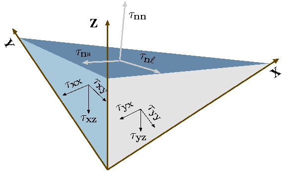
Figure 8.5: Stress diagram on a tetrahedron shape.
Suppose that a straight angle tetrahedron is under stress as shown in Figure 8.5. The forces balance in the \(x\) direction excluding the slanted surface is
\[
\label{dif:eq:transformationTau}
F_x = -\tau_{yx} \delta A_y - \tau_{xx} \delta A_x - \tau_{zx}\delta A_z
\]
where \(\delta A_y\) is the surface area of the tetrahedron in the \(y\) direction, \(\delta A_x\) is the surface area of the tetrahedron in the \(x\) direction and \(\delta A_z\) is the surface area of the tetrahedron in the \(z\) direction. The opposing forces which acting on the slanted surface in the \(x\) direction are
\[
\label{dif:eq:transformationTauS}
F_x = \delta A_n \left( \tau_{nn} \,\widehat{n}\cdot\widehat{i}
- \tau_{nll} \,\widehat{ll}\cdot\widehat{i}
- \tau_{n\aleph} \,\,\widehat{\aleph}\cdot\widehat{i} \right)
\]
Where here \(\widehat{\aleph}\), \(\widehat{ll}\) and \(\widehat{n}\) are the local unit coordinates on \(n\) surface the same can be written in the \(x\), and \(z\) directions. The transformation matrix is then
\[
\label{dif:eq:transformationM}
\left(
\begin{array}{c}
F_x \\ F_y \\ F_x
\end{array}
\right) =
\left(
\begin{array}{rrcll}
\widehat{n}\cdot\widehat{i} & & \widehat{ll}\cdot\widehat{i} & & \widehat{\aleph}\cdot\widehat{i}\\
\widehat{n}\cdot\widehat{j} & & \widehat{ll}\cdot\widehat{j} & & \widehat{\aleph}\cdot\widehat{j}\\
\widehat{n}\cdot\widehat{k} & & \widehat{ll}\cdot\widehat{k} & & \widehat{\aleph}\cdot\widehat{k}
\end{array}
\right) \delta A_n
\]
When the tetrahedron is shrunk to a point relationship of the stress on the two sides can be expended by Taylor series and keeping the first derivative. If the first derivative is neglected (tetrahedron is without acceleration) the two sides are related as
\[
\label{dif:eq:tetrahedron}
-\tau_{yx} \delta A_y - \tau_{xx} \delta A_x - \tau_{zx}\delta A_z = \delta A_n \left( \tau_{nn}
\,\widehat{n}\cdot\widehat{i}
- \tau_{nll} \,\widehat{ll}\cdot\widehat{i}
- \tau_{n\aleph} \,\,\widehat{\aleph}\cdot\widehat{i} \right)
\]
The same can be done for \(y\) and \(z\) directions. The areas are related to each other through angles. These relationships provide the transformation for the different orientations which depends only angles of the orientations. This matrix is referred to as stress tensor and as it can be observed has nine terms.
The Symmetry of the Stress Tensor
A small liquid cubical has three possible rotation axes. Here only one will be discussed the same conclusions can be drown on the other direction. The cubical rotation can involve two parts: one distortion and one rotation . A finite angular distortion of infinitesimal cube requires an infinite shear which required for infinite moment. Hence, the rotation of the infinitesimal fluid cube can be viewed as it is done almost as a solid body rotation. Balance of momentum around the \(z\) direction shown in Figure 8.6 is
\[
\label{dif:eq:cubeM}
M_z = I_{zz} \dfrac{d\theta}{dt}
\]
Where \(M_z\) is the cubic moment around the cubic center and \(I_{zz}\) is the moment of inertia around that center. The momentum can be asserted by the shear stresses which act on it. The shear stress at point \(x\) is \(\tau_{xy}\). However, the shear stress at point \(x+dx\) is
\[
\label{dif:eq:tauxydx}
\left. \tau_{xy} \right|_{x+dx} = \tau_{xy} + \dfrac{d\tau_{xy}}{dx}dx
\]
Fig. 8.6 Diagram to analysis the shear stress tensor.
The same can be said for \(\tau_{yx}\) for \(y\) direction. The clarity of this analysis can be improved if additional terms are taken, yet it turn out that the results will be the same. The normal body force (gravity) acts through the cubic center of gravity. The moment that created by this action can be neglected (the changes are insignificant). However, for cases that body force, such as the magnetic fields, can create torque. For simplicity and generality, it is assumed that the external body force exerts a torque \(G_T\) per unit volume at the specific location. The body force can exert torque is due to the fact that the body force is not uniform and hence not act through the mass center.
Advance Material
The shear stress in the surface direction potentially can result in the torque due to the change in the shear stress. For example, \(\tau_{xx}\) at \(x\) can be expended as a linear function
\[
\label{dif:eq:txxAtX}
\tau_{xx} = \left. \tau_{xx} \right|_y + \left. \dfrac{d\tau_{xx}}{dy} \right|_y \eta
\]
where \(\eta\) is the local coordinate in the \(y\) direction stating at \(y\) and "mostly used'' between \(y \) \textlesslt \(\eta\) \textlesslt \(y+dy\).
Fig. 8.7 The shear stress creating torque.
The moment that results from this shear force (clockwise positive) is
\[
\label{dif:eq:tauxxM}
\int_y^{y+dy} \tau_{xx}(\eta)\,\left(\eta - \dfrac{dy}{2\dfrac{}{}} \right) d\eta
\]
Substituting (11) into (12) results
\[
\label{dif:eq:tauOneSideM}
\int_y^{y+dy} \left( \left. \tau_{xx} \right|_y + \left. \dfrac{d\tau_{xx}}{dy\dfrac{}{}} \right|_y \eta\right)
\,\left(\eta - \dfrac{dy}{2\dfrac{}{}} \right) d\eta
\]
The integral of (13) isn't zero (non symmetrical function around the center of integration). The reason that this term is neglected because on the other face of the cubic contributes an identical term but in the opposing direction (see Figure 8.6)
End Advance Material
The net torque in the z-direction around the particle's center would then be
\[
\label{dif:eq:tauTourque}
\begin{array}{rcl}
\left( \tau_{yx} \right) \dfrac{dx\,dy\,dz}{2} - &
\left( \tau_{yx} + \dfrac{\partial \tau_{xy}}{\partial x\dfrac{}{}} \right) \dfrac{dx\,dy\,dz}{2} +
\left( \tau_{xy} \right) \dfrac{dx\,dy\,dz}{2} -
& \\ &
\left( \tau_{xy} + \dfrac{\partial \tau_{xy}}{\partial x\dfrac{}{}} \right) \dfrac{dx\,dy\,dz}{2}
= \overbrace{\rho\,dx\,dy\,dz\left((dx)^2 + (dy)^2 \right)}^{I_{zz}} \dfrac{d\theta}{dt}
\end{array}
\]
The actual components which contribute to the moment are
\[
\label{dif:eq:tauTourqueD}
G_T+
\tau_{xy} - \tau_{xy} +
\overbrace{\dfrac{\partial \left( \tau_{yx} - \tau_{xy}\right)}{\partial y}}^{\cong 0}
= \rho \dfrac{\underbrace{\left((dx)^2 + (dy)^2 \right)}_{\scriptsize =0}}{12} \dfrac{d\theta}{dt}
\]
\[
\label{dif:eq:tauTourqueF}
G_T+
\tau_{xy} = \tau_{yx}
\]
This analysis can be done on the other two directions and hence the general conclusion is that
\[
\label{dif:eq:tauij}
G_T+ \tau_{ij} = \tau_{ji}
\]
where \(i\) is one of \(x,y,z\) and the \(j\) is any of the other \(x,y, z\). For the case of \(G_T= 0\) the stress tensor becomes symmetrical. The gravity is a body force that is considered in many kind of calculations and this force cause a change in symmetry of the stress tensor. However, this change, for almost all practical purposes, can be neglected. The magnetic body forces on the other hand are significant and have to be included in the calculations. If the body forces effect is neglected or do not exist in the problem then regardless the coordinate system orientation
\[
\label{dif:eq:tauSymmetry}
\tau_{ij} = \tau_{ji} \qquad (i \neq j)
\]
Contributors and Attributions
Dr. Genick Bar-Meir. Permission is granted to copy, distribute and/or modify this document under the terms of the GNU Free Documentation License, Version 1.2 or later or Potto license.
yxδAy−τxxδAx−τzxδAz=δAn(τnnnˆ⋅iˆ−τnllllˆ⋅iˆ−τnℵℵˆ⋅iˆ)(8)