
7: Accelerated Performance - Takeoff and Landing
- Page ID
- 75452

\( \newcommand{\vecs}[1]{\overset { \scriptstyle \rightharpoonup} {\mathbf{#1}} } \)
\( \newcommand{\vecd}[1]{\overset{-\!-\!\rightharpoonup}{\vphantom{a}\smash {#1}}} \)
\( \newcommand{\dsum}{\displaystyle\sum\limits} \)
\( \newcommand{\dint}{\displaystyle\int\limits} \)
\( \newcommand{\dlim}{\displaystyle\lim\limits} \)
\( \newcommand{\id}{\mathrm{id}}\) \( \newcommand{\Span}{\mathrm{span}}\)
( \newcommand{\kernel}{\mathrm{null}\,}\) \( \newcommand{\range}{\mathrm{range}\,}\)
\( \newcommand{\RealPart}{\mathrm{Re}}\) \( \newcommand{\ImaginaryPart}{\mathrm{Im}}\)
\( \newcommand{\Argument}{\mathrm{Arg}}\) \( \newcommand{\norm}[1]{\| #1 \|}\)
\( \newcommand{\inner}[2]{\langle #1, #2 \rangle}\)
\( \newcommand{\Span}{\mathrm{span}}\)
\( \newcommand{\id}{\mathrm{id}}\)
\( \newcommand{\Span}{\mathrm{span}}\)
\( \newcommand{\kernel}{\mathrm{null}\,}\)
\( \newcommand{\range}{\mathrm{range}\,}\)
\( \newcommand{\RealPart}{\mathrm{Re}}\)
\( \newcommand{\ImaginaryPart}{\mathrm{Im}}\)
\( \newcommand{\Argument}{\mathrm{Arg}}\)
\( \newcommand{\norm}[1]{\| #1 \|}\)
\( \newcommand{\inner}[2]{\langle #1, #2 \rangle}\)
\( \newcommand{\Span}{\mathrm{span}}\) \( \newcommand{\AA}{\unicode[.8,0]{x212B}}\)
\( \newcommand{\vectorA}[1]{\vec{#1}} % arrow\)
\( \newcommand{\vectorAt}[1]{\vec{\text{#1}}} % arrow\)
\( \newcommand{\vectorB}[1]{\overset { \scriptstyle \rightharpoonup} {\mathbf{#1}} } \)
\( \newcommand{\vectorC}[1]{\textbf{#1}} \)
\( \newcommand{\vectorD}[1]{\overrightarrow{#1}} \)
\( \newcommand{\vectorDt}[1]{\overrightarrow{\text{#1}}} \)
\( \newcommand{\vectE}[1]{\overset{-\!-\!\rightharpoonup}{\vphantom{a}\smash{\mathbf {#1}}}} \)
\( \newcommand{\vecs}[1]{\overset { \scriptstyle \rightharpoonup} {\mathbf{#1}} } \)
\(\newcommand{\longvect}{\overrightarrow}\)
\( \newcommand{\vecd}[1]{\overset{-\!-\!\rightharpoonup}{\vphantom{a}\smash {#1}}} \)
\(\newcommand{\avec}{\mathbf a}\) \(\newcommand{\bvec}{\mathbf b}\) \(\newcommand{\cvec}{\mathbf c}\) \(\newcommand{\dvec}{\mathbf d}\) \(\newcommand{\dtil}{\widetilde{\mathbf d}}\) \(\newcommand{\evec}{\mathbf e}\) \(\newcommand{\fvec}{\mathbf f}\) \(\newcommand{\nvec}{\mathbf n}\) \(\newcommand{\pvec}{\mathbf p}\) \(\newcommand{\qvec}{\mathbf q}\) \(\newcommand{\svec}{\mathbf s}\) \(\newcommand{\tvec}{\mathbf t}\) \(\newcommand{\uvec}{\mathbf u}\) \(\newcommand{\vvec}{\mathbf v}\) \(\newcommand{\wvec}{\mathbf w}\) \(\newcommand{\xvec}{\mathbf x}\) \(\newcommand{\yvec}{\mathbf y}\) \(\newcommand{\zvec}{\mathbf z}\) \(\newcommand{\rvec}{\mathbf r}\) \(\newcommand{\mvec}{\mathbf m}\) \(\newcommand{\zerovec}{\mathbf 0}\) \(\newcommand{\onevec}{\mathbf 1}\) \(\newcommand{\real}{\mathbb R}\) \(\newcommand{\twovec}[2]{\left[\begin{array}{r}#1 \\ #2 \end{array}\right]}\) \(\newcommand{\ctwovec}[2]{\left[\begin{array}{c}#1 \\ #2 \end{array}\right]}\) \(\newcommand{\threevec}[3]{\left[\begin{array}{r}#1 \\ #2 \\ #3 \end{array}\right]}\) \(\newcommand{\cthreevec}[3]{\left[\begin{array}{c}#1 \\ #2 \\ #3 \end{array}\right]}\) \(\newcommand{\fourvec}[4]{\left[\begin{array}{r}#1 \\ #2 \\ #3 \\ #4 \end{array}\right]}\) \(\newcommand{\cfourvec}[4]{\left[\begin{array}{c}#1 \\ #2 \\ #3 \\ #4 \end{array}\right]}\) \(\newcommand{\fivevec}[5]{\left[\begin{array}{r}#1 \\ #2 \\ #3 \\ #4 \\ #5 \\ \end{array}\right]}\) \(\newcommand{\cfivevec}[5]{\left[\begin{array}{c}#1 \\ #2 \\ #3 \\ #4 \\ #5 \\ \end{array}\right]}\) \(\newcommand{\mattwo}[4]{\left[\begin{array}{rr}#1 \amp #2 \\ #3 \amp #4 \\ \end{array}\right]}\) \(\newcommand{\laspan}[1]{\text{Span}\{#1\}}\) \(\newcommand{\bcal}{\cal B}\) \(\newcommand{\ccal}{\cal C}\) \(\newcommand{\scal}{\cal S}\) \(\newcommand{\wcal}{\cal W}\) \(\newcommand{\ecal}{\cal E}\) \(\newcommand{\coords}[2]{\left\{#1\right\}_{#2}}\) \(\newcommand{\gray}[1]{\color{gray}{#1}}\) \(\newcommand{\lgray}[1]{\color{lightgray}{#1}}\) \(\newcommand{\rank}{\operatorname{rank}}\) \(\newcommand{\row}{\text{Row}}\) \(\newcommand{\col}{\text{Col}}\) \(\renewcommand{\row}{\text{Row}}\) \(\newcommand{\nul}{\text{Nul}}\) \(\newcommand{\var}{\text{Var}}\) \(\newcommand{\corr}{\text{corr}}\) \(\newcommand{\len}[1]{\left|#1\right|}\) \(\newcommand{\bbar}{\overline{\bvec}}\) \(\newcommand{\bhat}{\widehat{\bvec}}\) \(\newcommand{\bperp}{\bvec^\perp}\) \(\newcommand{\xhat}{\widehat{\xvec}}\) \(\newcommand{\vhat}{\widehat{\vvec}}\) \(\newcommand{\uhat}{\widehat{\uvec}}\) \(\newcommand{\what}{\widehat{\wvec}}\) \(\newcommand{\Sighat}{\widehat{\Sigma}}\) \(\newcommand{\lt}{<}\) \(\newcommand{\gt}{>}\) \(\newcommand{\amp}{&}\) \(\definecolor{fillinmathshade}{gray}{0.9}\)Chapter 7. Accelerated Performance: Takeoff and Landing
Introduction
To this point, all of our discussion has related to static or unaccelerated flight where F = ma = 0. Even in climb and descent we assumed “quasi-level” conditions where the forces on the aircraft summed to zero. If we are to look at the performance of an airplane during take‑off and landing we must, for the first time, consider acceleration (during takeoff) and deceleration (during landing). We will also have a couple of new forces to consider in the ground reaction force and ground friction.
In take-off, the airplane accelerates from zero groundspeed (but not necessarily zero airspeed!) to a speed at which it can lift itself from the ground. The thrust must exceed drag for acceleration to take place and the lift won’t equal weight until the moment of liftoff. The plane may accelerate along the ground at a given angle of attack (or lift coefficient) until the speed reaches the point where the dynamic pressure combines with the lift coefficient to give lift equal to the weight or it may accelerate at some angle of attack determined by its landing gear height until it reaches a speed which will give lift equals to weight when the aircraft is then rotated (tail down, nose up) to a higher angle of attack and lift coefficient.
Any pilot will tell you that take‑off and landing are what flight is all about. The thrill of full throttle and maximum acceleration as the plane roars down the runway, followed by the freeing of the soul which comes from cheating gravity and breaking the bond with the earth is incomparable. Of course the pilot hopes this occurs before the end of the runway is reached and in such a way as to allow clearance of the water tower at the end of the strip!
In landing, deceleration must be provided through braking, aerodynamic drag, ground friction and possibly reverse thrust to slow the plane to zero speed; hopefully before it reaches the end of the runway!
Landing is the ultimate challenge of person against nature as the pilot once again attempts to remain in control of a planned encounter with the ground in a vehicle moving at speeds which can result in instant mutilation and death if there is the slightest miscalculation of crosswind or downdraft. Of course, all of this must be done in such a manner as to assure the passenger that every move is as safe and natural and controlled as a Sunday afternoon drive to the golf course.
Wind will be a factor in take‑off and landing and one would think it would be obvious that the pilot should position the aircraft at the end of the runway which will result in operation into the wind. This will result in a reduction in the length of the ground roll in either take‑off or landing. To some, however this may not be obvious.
The author once sat on a graduate committee of a student in Transportation Engineering who had taken several courses in airport design. When asked what role the prevailing winds played in the design of airports the student appeared puzzled. Given a hint that it had something to do with the way the runways were aligned, he still drew a blank. Finally, when asked to draw a runway and show an airplane getting ready to take‑off at one end and to explain which way the wind would be blowing, the student’s eyes lit up in an apparent revelation of truth. He drew the runway horizontal across the center of the blackboard with the airplane at the right end, ready to begin a take‑off roll toward the left. Then he triumphantly drew an arrow to indicate a wind moving from right‑to‑left, the same direction as the motion of the aircraft!
As despair and gloom settled over the faculty in the room I, rather reluctantly, asked him why the airplane would take‑off in the same direction as the wind blew. He replied that the answer was obvious, “So the wind will carry the pollution away with the airplane!” Watch out for environmentalists who design airports!
To study aircraft performance in take‑off and landing we must make sure we have proper definitions of what these phases of flight entail. Then we must consider the forces acting on the airplane. We will begin this study by looking at take‑off.
7.1 Takeoff Performance
The definition used by the Federal Aviation Administration for take‑off includes the ground run from zero ground speed to the point where the wheels leave the ground, plus the distance required to clear a 50 foot obstacle. The distance over the ground for all of the above is computed at maximum gross weight at sea level standard conditions. The “worst case” condition is often also calculated for a hot day at high altitude (100ºF in Denver).
We will concern ourselves only with the ground run portion of the take‑off run, knowing that we can find the distance to clear a 50 foot obstacle from our climb equations. That climb would be calculated for maximum angle of climb conditions.
The first step in the calculation of the ground run needed for take‑off is an examination of the forces on the aircraft. In addition to the lift, drag, thrust and weight, we must now consider the ground friction and the “Resultant” force of the ground in supporting all or part of the weight of the aircraft. These are shown in the figure below. The coefficient of friction will depend on the ground surface and braking friction.
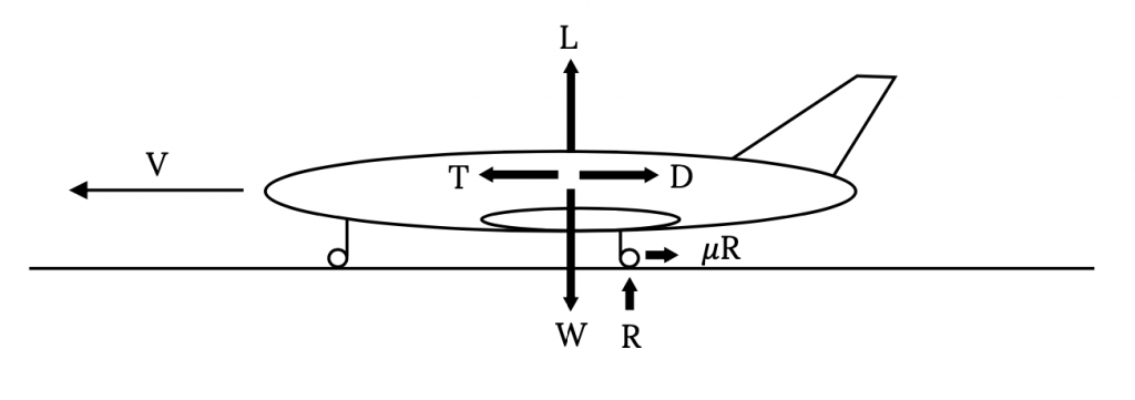
A summation of the vertical forces in Figure 7.1 gives
L + R ‑ W = 0
or
R = W ‑ L
Summing the horizontal forces gives

Note that in the above relation we have, for the first time, an acceleration. These forces change as the aircraft accelerates from rest to take‑off speed.
Combining the two equations above we have a single relation
=[W/g][dV/dt]")
which can be rearranged to give
−μ]−(g/W)[D−μL]=dV/dt")
Our desire is to integrate this or a related equation to get the time and distance needed for the take‑off ground run. To do this we must first account for the dependence of both lift and drag on velocity. This gives
where CLg denotes the lift coefficient during the takeoff or landing ground run and not that in flight or at the point of takeoff or touchdown itself.
The above equation still contains thrust and weight, both of which may well change during the take‑off ground run. Thrust is known to be a function of velocity, however, weight will be a function of the rate of fuel use (specific fuel consumption) and will be a function of time rather than speed. In order to keep our analysis relatively simple we will consider the weight change during the take‑off roll to be negligible and treat weight as a constant in the equation. We will use the thrust model which we derived from the Momentum Equation in Chapter 2,
T = T0 -aV2
In this equation T0 is the thrust at zero velocity or the “static thrust”, a is a constant (which could be zero) and T is the thrust at any speed. Substituting this model for thrust into our acceleration equation gives:
It should be noted that the velocity in this equation is the airspeed and not the speed relative to the ground. When we look at the take‑off distance we will have to be concerned with both the ground speed and the airspeed. The simplest case will be when there is no ground wind; ie, when the airspeed and ground speed are equal.
In the above relation all of the terms in brackets and parentheses are essentially constant for a given aircraft at a given runway altitude and for a given runway surface. The lift coefficient is given the special designation of CLg to denote that it is the value for the ground run only. In a normal take‑off roll the airplane accelerates to a pre-determined speed and then “rotates” to a higher angle of attack which will produce enough lift to result in lift‑off at that speed. Hence, the ground run lift coefficient will probably not be the same as the take‑off lift coefficient. The drag coefficient could be similarly subscripted; however, since CD is a function of CL and will subsequently be written in that manner, this will not be done at this point.
Since most of the terms in the equation can be treated as constants the equation can be simplified as follows:
dV/dt = A – BV2 ,
where
and
This acceleration relationship can be integrated to obtain the time for the ground run of take‑off.

Assuming that the airplane starts the take‑off run from rest and that there is no ground wind and that the upper limit is the take‑off velocity VTO, we have
=time for take – off.")
NOTE: This may be the first time that the reader has ever seen an inverse hyperbolic tangent. What should follow is a frantic search of your calculator to see if there is any such key or combination of keys along with an equally harried check of the indices of high school and college trig and calculus texts to see just what the heck this thing is. Waiting to figure this out during a test could result in considerable embarrassment.
A question which should be considered here is “What is a good value for the take‑off speed?”
The very lowest speed at which the airplane can possibly lift off of the ground is the stall speed for straight and level flight at the runway altitude. It is, however, not safe to attempt takeoff at this minimum speed with the airplane right on the verge of stall. A somewhat higher than stall speed will give a margin of safety which will allow take‑off at a fairly low speed without risk of stall due to unexpected gusts or similar problems. Commonly used values for take-off speed range from 10 to 20 percent higher than straight and level stall speed.
1.1 Vstall < VTO < 1.2 Vstall .
We will assume the higher value,
VTO = 1.2 Vstall ,
unless told otherwise.
Far more important than the time required for the take-off ground run is the distance required. It is always nice to know that the pilot can get the airplane into the air before it reaches the end of the runway! To find the take‑off distance we must integrate over distance instead of time.
dV/dS = (dV/dt)/dS/dt) = (A – BV2) / V
Rearranging this gives

which is integrated to get

Finally
")
Now, assuming that the airplane starts from rest, no wind and lift off at VTO we have
")
We will later investigate the case of take‑off in a wind.
Before going further with an analytical analysis of the takeoff ground run it is worthwhile to pause and examine the physical aspects of the problem. These are too often lost in the equations, especially when we have hidden a lot of terms behind convenient terms like A and B. Let’s first write the last equation for take‑off distance in its full glory.
It is obvious from the above equation that many factors influence the take-off distance.
It is, for example, intuitive that the ground friction will retard take‑off. The retarding force due to friction will decrease as the lift increases during the take‑off run. So, it appears that it might be to our advantage to move down the runway at a high angle of attack such that high lift is generated which will result in a reduction in the friction force and enhance the airplane’s acceleration to take‑off speed. On the other hand, a high angle of attack will also give a high drag coefficient, retarding acceleration. At some point in the take‑off run the drag force will exceed the friction force. Does this mean the pilot should begin the take‑off run at a high angle of attack and then lower it to reduce drag so as to hold some friction/drag ratio at an optimal value?
What about the value of the friction coefficient? Do we use one type of ground run on a concrete runway and another on a grass strip? What about soft dirt? Typical values of friction coefficient are:
Table 7.1: Typical Values of Friction Coefficients
| Concrete, asphalt | 0.02 - 0.05 |
| Hard Turf | 0.04 - 0.05 |
| Normal turf, short grass | 0.05 |
| Normal turf, long grass | 0.07 - 0.10 |
| Soft ground | 0.10 - 0.30 |
One should probably use the lower of the above values for a particular surface unless instructed to do otherwise.
For a “soft field” take‑off such as on long grass or soft ground, pilots are taught to do several things to reduce the role of ground friction on the take‑off roll. Usually, the use of flaps is recommended to increase the lift coefficient and, if the airplane has a tricycle type of landing gear (nose wheel and two main wheels), the pilot is taught to keep the nose up, which will both reduce the friction on that wheel and give a higher angle of attack and lift coefficient. One reason for the popularity of the “tail dragger” style of aircraft in the early days of aviation was it’s natural superiority in soft field takeoffs, which were common at the airfields of the day.
7.2 Minimum take-off ground run:
In a normal take‑off, as mentioned earlier, the aircraft accelerates along the runway at a fairly constant angle of attack until the desired take‑off speed is reached. The plane is then rotated to give an increased angle of attack and lift coefficient such that lift equals or exceeds the weight, allowing lift‑off. The angle of attack during that ground roll and, hence the lift and drag coefficients, is largely determined by the relative lengths of the landing gear and the angle at which the wing is attached to the fuselage.
Many factors influence the size and placement of the landing gear. It is nice if the gear struts are long enough to keep the propeller from hitting the runway (this can be a real problem with a tail mounted prop) and it is also good if the center of gravity of the aircraft is between the main and auxillary gear. The main gear should be close to the CG to allow ease of rotation but far enough away to prevent inadvertent rotation. There is also the question of where the gear are stored in a retractable system
The wing angle of placement on the fuselage will primarily be a function of optimal cruise considerations such that things like the fuselage drag is minimized and pilot visibility is satisfactory when the wing is at the best combination of lift and drag coefficient for cruise as determined by using relations of previous chapters. It is also nice if, in cruise conditions, the aisle in a commercial aircraft is relatively level.
An important task for the designer is to find the wing angle of attack which will minimize the take‑off ground run and then to design the landing gear such that under normal conditions the plane sits on its gear with the wing at that angle. Let’s try to find that angle or, more precisely, the lift and drag coefficients at that angle of attack.
We first return to the equation for acceleration in the ground run.
![dVdt=g(T0W−μ)−gW⌊12ρS(CD−μCLg)+a]V2](https://eng.libretexts.org/@api/deki/files/49378/4ec8df9107c7ece11bb86a29e83f5666.png?revision=1 "dVdt=g(T0W−μ)−gW⌊12ρS(CD−μCLg)+a]V2")
Our desire is to maximize this acceleration at all times during the run. Assuming that the only variable we have is angle of attack, i.e., CL and CD, assuming that we have a parabolic drag polar, and further assuming that the take‑off speed VTO is independent of CLg, we can find the maximum acceleration by taking the derivative with respect to CLg and equating the result to zero. The assumption that VTO is independent of CLg means that the plane will be rotated at VTO to achieve lift off rather than allowed to continue to accelerate until lift off occurs at CLg.
=ddCL(CD−μCLg)=ddCL(CDO+KCLg2−μCLg)=0")
or

This gives the best value of the ground run lift coefficient for minimum ground run length.

7.2.1 Airplane design note
This tells us that if we want to take-off in the shortest possible ground run distance we will design the airplane so that with a normal load distribution on the runway its wing will be at the angle of attack which will give the above value of lift coefficient. We may be able to do this by making the wheel struts or supports the right length. In other words, a well designed airplane will have its wing attached to the fuselage at an angle so the fuselage is level at cruise conditions and will have its landing gear height set to put the wing at the optimum take-off angle of attack at maximum gross weight conditions when sitting on the ground.
It might be interesting to see just how much difference having the optimum ground run lift coefficient makes by finding the best CLg for takeoff and then calculating the resulting takeoff distance as well as the distance at somewhat higher and lower values of CL.
7.2.2 Power based engine performance
A factor not previously noted in this discussion is that we have accounted for the output of the aircraft’s propulsion system in terms of thrust and not power. This was natural because we were dealing with force equations. What do we do when we have an aircraft which has a power based propulsion system (propeller)? We know that thrust is equal to power divided by velocity but how do we use that in the equations? Perhaps an example will provide an answer:
EXAMPLE 7.1
For an aircraft with the following properties find the minimum ground run distance at sea level standard conditions.
W = 56,000 lb
VTO = 1.15 Vstall
ηp = 0.75
S = 1000 sq. ft.
CD = 0.024 + 0.04CL2
TO= 13000 lb
CLmax = 2.2
μ = 0.025
Ps = 4800 hp
Let’s first find the stall speed and then the take‑off speed.
/(ρSCL)]1/2=146fps")
VTO = 1.15 Vstall = 168 fps.
Now we must face the problem of having power information and equations that demand thrust data. We have been given the static thrust and we can assume that the power available which was given will be the power in use at the moment of take‑off. We then have to determine how thrust varies and how to fit it to our assumed thrust versus velocity relation used in the take‑off acceleration equation.
At take-off speed
=3600hp")
so, the thrust at take off is
TTO = Pav/VTO = 3600 hp / 168 fps = (1980000 ft-lb/sec) / 168 fps = 11786 lb
Our thrust versus velocity relationship is
T = T0 -aV2.
Substituting the takeoff speed and thrust and the static thrust we can find the value for a.
11786 lb = 13000 lb – a (168 fps)2
a = 0.0430 lb-sec2/ft2
Our thrust relationship to be used in the take‑off equations is then
T = 1300 – 0.0430 V2.
Now we need to determine the lift coefficient for minimum ground run.

The drag coefficient at the minimum ground run lift coefficient is:
CD = CD0 + KCL2 = 0.024 + 0.04(0.3125)2 = 0.0279
Finally we can use all of the above to determine the take‑off ground run.
")
=32.2ft/sec2(1300056000−0.025)=6.65ft/sec2")
![B=gW[12ρS(CD−μCLg)+a]=3.80×10−5ft−1](https://eng.libretexts.org/@api/deki/files/49387/dd5b8a7d5224717b1421c37d86270d57.png?revision=1 "B=gW[12ρS(CD−μCLg)+a]=3.80×10⁻⁵ft−1")
ft×ln6.656.65−(3.8×10⁻⁵)(168)2")
S = 2314 ft.
7.3 Takeoff Without Rotation
As described previously, a conventional take‑off run would be made at the angle of attack dictated by the airplane configuration and the landing gear geometry, all of which has probably been designed to give near optimal ground run acceleration. When a predetermined take‑off speed is reached the pilot raises the nose of the aircraft to increase the angle of attack and give the lift needed for lift‑off. But, what would happen if, instead of rotating, the airplane was allowed to simply continue to accelerate until it gained enough speed to lift off without rotation?
Continued ground run acceleration to take‑off without rotation is not an optimum way to achieve flight. It will always require more runway than a conventional take‑off. There are, however, a limited number of aircraft which are designed for this type of lift-off. One well known example is the B-52 bomber. This aircraft has what might be described as “bicycle” type landing gear with the gear located entirely in the long fuselage and placed well fore and aft the center of gravity. This placement and the long, low fuselage make rotation virtually impossible. The result is the need for very long runways and very long, shallow approaches to landing.
Optimizing the takeoff run for an aircraft like the B-52 is different from the maximum acceleration optimum for a conventional take-off. Since the plane cannot rotate, the gear design and wing placement on the fuselage must be arranged such that the wing angle of attack is that desired for a safe and efficient lift-off. Too high an angle of attack might result in take-off at conditions too near stall and too low an angle might require too much runway. In the following example we look at such an aircraft where the design is such that the ground run angle of attack of the wing is set to give take-off at a speed 20% above stall speed.
EXAMPLE 7.2
The aircraft defined below is designed for take-off with no rotation, thus the ground run angle of attack (and, therefore, CL and CD) is the same as that at take-off. Find the take-off distance at sea level standard conditions.
W = 75,000 lb
CD = 0.02 + 0.05CL2
μ = 0.02
S = 2500 sq. ft.
CLmax = 1.5
T = T0 = 12,000 lb
VTO = 1.2 VSTALL
We must first find the stall speed, the take-off speed, and the related take-off (and, thus, ground run) lift coefficient.
/(ρSCLmax)]1/2=129.7fps")
VTO = 1.2 Vstall = 155.7 fps.
We can then find the lift coefficient for this take-off speed.
=1.042")
Actually we could have skipped some of the above as we realized the following.:
CLg = CLTO = [Vstall/VTO]2 CLmax = [1/1.2]2 (1.5) = 1.042
Using the above lift coefficient we find the drag coefficient.
CD = CD0 + KCL2 = 0.02 + 0.05(1.042)2 = 0.0742
We are now ready to find the takeoff distance.
")
=4.54ft/sec2")
![B=gW[12ρS(CD−μCLg)+a]=6.85×10−5ft−1](https://eng.libretexts.org/@api/deki/files/49393/614672409199cd49b5801e08e421f093.png?revision=1 "B=gW[12ρS(CD−μCLg)+a]=6.85×10⁻⁵ft−1")
ln(4.544.54−(6.85×10⁻⁵)(155.7)2)")
S = 3324 ft.
7.4 Thrust Augmented Take-off
Although not commonly seen today, a technique once regularly used by military cargo aircraft and bombers like the B‑52 to reduce the take‑off distance involved the augmentation of ground run thrust through the use of strap‑on or built in solid rockets. This system was often referred to as JATO for jet assisted take‑off even though it used rockets and not jets. Calculation of ground runs for this type of take‑off require breaking the ground run distance integral into two parts to account for the two different levels of thrust used in the run. The resulting equation is as follows:
![STO=12Bln[AA−B(VTO2)2]+12Bln[A1−B(VTO2)2A1−BVTO2]](https://eng.libretexts.org/@api/deki/files/49395/dc1433e03f724dc0a53e241076bba3d2.png?revision=1 "STO=12Bln[AA−B(VTO2)2]+12Bln[A1−B(VTO2)2A1−BVTO2]")
.")
Let us return to the last example and see what happens if we try to shorten the ground run of this airplane by the use of 15,000 pounds of extra thrust obtained from JATO units which are fired for the first ten seconds of the ground run to boost the plane’s initial acceleration.
The total thrust during the first ten seconds of the ground run will be 27,000 pounds. Thus, for that portion of the run the A term in the ground run distance equation will be
=32.2(27007500−0.02)=11.0ft/sec2")
The B term will not be changed.
Now we must determine the velocity of the aircraft at the end of this first ten seconds of acceleration since the limits on the distance equation are velocities. To find this we go to the relationship for take‑off ground run time
−tanh−1(V0BA)⌋")
Since the initial velocity is zero and t1 – t2 = 10 sec we have
")
Solving gives the speed at the end of the augmented thrust portion of the take‑off run.
V1 = 107 fps.
At this point it wouldn’t hurt to check the units in the equations above and make sure that we really did end up with units of feet per second.
The entire distance for take‑off can now be found as follows:
=540ft")
=1939ft")
STOTAL = 2480 ft.
The JATO boost in this example gave a 25% reduction in the ground run needed for takeoff. This could be important for such an aircraft if it is operating out of short, remote airfields often found in “third world” countries or in military operations.
7.5 Ground Wind Effects
Earlier we mentioned the importance of ground wind in the take‑off of aircraft. It is rare that a ground wind does not exist, thus, our “no‑wind” equations are, hopefully, worst case predictions since taking off into the wind will reduce the distance for the ground run. Finding the distance required for take‑off into a ground wind (assuming the pilot has the good sense to fly into the wind and not attempt a “downwind” take‑off) requires another look at the equations. Note: There are sometimes conditions such as “downhill” runways or end‑of‑runway obstacles which may at times necessitate a downwind takeoff.
In the take‑off equations it is important to realize that, as noted when first presented, the distance and acceleration are measured relative to the ground; however, the aerodynamic forces in the equations are obviously dependent on airspeed and not ground speed. We must consider this in our equations. In doing so we will use the following designations for different speeds:
VG = GROUND SPEED
VA = AIRSPEED
VW = WIND SPEED (PARALLEL TO RUNWAY)
This gives
VA = VG ± VW (+ if a head wind, – if a tail wind).
Returning to the basic equation of motion we have
dVG/dt = A – BVA2
However,

Thus
dVG/dt = dVA/dt = A – BVA2 .
So, to determine the time for take‑off we use
dt = dVA /(A – BVA2) .
To find take‑off distance we use

or

This becomes
dVAdS=dVAdt=A−BVA2")
Finally we have a differential which includes wind effects. We will write it only for the case of the headwind since this would be the normal situation.

Now, we must also note that the take‑off speed of the aircraft is airspeed and not ground speed. The time and distance equations above may be integrated above to give
−tanh−1(VA1BA)⌋S2−S1=12Bln(A−BVA12A−BVA22)−VW(t2−t1)")
Finally, realizing that take‑off usually starts from rest at zero ground speed (at t = 0), we obtain
![t=1AB⌊tanh−1(VATOBA)−tanh−1(VWBA)]S=12Bln(A−BVW2A−BVATO2)−Vwt](https://eng.libretexts.org/@api/deki/files/49408/79417f2457e4e5181a1778ee6cc11110.png?revision=1 "t=1AB⌊tanh−1(VATOBA)−tanh−1(VWBA)]S=12Bln(A−BVW2A−BVATO2)−Vwt")
Note that the take‑off speed in these equations is the airspeed for takeoff and not the ground speed.
7.6 Landing
Landing, like take‑off, is properly defined as having at least two parts; an “approach” over a 50 foot obstacle to touchdown and the landing ground run. These, in turn, might be divided into several other segments. The approach will usually not be a non‑powered glide as studied earlier. The normal approach to landing for most aircraft is a powered descent. The FAA definition of the landing terminal glide over an obstacle is, however based on an unpowered glide as the limiting case. We have already considered gliding flight and should be able to deal with this portion of flight. A real descent can be the most interesting portion of the flight for a pilot as he of she corrects for side‑winds, updrafts, and downdrafts while aiming for a hoped‑for touchdown point on the runway. All of this is done at a descent rate of about 500 feet per minute (about 8 mph).
Here we will concern ourselves with only the touchdown through full stop portion of the landing. Again our primary concern will be ground run distance with the hope that full stop occurs before the end of the runway.
The equations of motion for the landing ground run are identical to those for takeoff, however, the terms in the equations can assume very different magnitudes from those in take‑off. To slow the aircraft in its landing ground run high drag is desirable, negative or “reverse” thrust may be used, and brakes will be used during much of the run to greatly increase the friction term. The boundary conditions on the integrals are essentially reversed with the initial speed being the touchdown or “contact” speed and the final ground speed being zero; however the solution may need to be broken into several segments to account for a sequence of events as part of the landing ground roll.
Before we look at the equations let’s look at a typical landing as seen by a small plane, general aviation pilot. The approach‑to‑landing descent will probably be made using full flaps, at least in its final “glide” (this will be true for almost any aircraft). This will lower the stall speed and allow approach and touchdown at a lower flight speed. It will also steepen the approach glide and, on the ground, add to the drag to help slow the aircraft.
As soon as the pilot feels that the aircraft is under full control after touchdown he or she may raise the flaps. While this reduces the drag and contributes to a longer ground roll, it also reduces the lift, increasing ground friction forces and allowing better directional control of the aircraft in a crosswind. After this is done the brakes will be applied to further slow the aircraft to a stop. Larger, jet aircraft may apply reverse thrust very soon after touchdown and before use of brakes to improve deceleration.
Now, let’s look again at the equations of motion for an aircraft on the ground. We can still use
dS = VdV / (A – BV2) .
We define VC as the speed of initial ground contact on landing at some point defined as S1 and conditions at the next point in the ground roll sequence as S2 and V2, giving the following integrated equation:
or
In the rare case where none of the parameters in the equation (T, μ, CLg, etc.) change during the ground run; i.e., where the airplane simply touches down and coasts to a stop, our final speed V2 = 0, giving
")
For a first estimate of a minimum landing ground run one could assume that the pilot is able to apply the brakes almost instantly after touchdown and that thrust is simply zero during the entire roll and, thus, use the above equation to calculate a landing ground roll distance. In reality, as mentioned previously, the ground roll would have to be determined by adding a series of the previous ΔS equations, each with its appropriate starting and ending speeds and values for thrust and friction and the like.

The time for the landing ground roll is found from
dV/dt = A – BV2
or

Integration of this equation can take several different forms depending on the relative magnitudes and signs of A and B. Looking again at these terms
")
![B=gW[12ρS(CD−μCLg)+a]](https://eng.libretexts.org/@api/deki/files/49415/3ca9ef333dce2343b151d0152f4bb5e6.png?revision=1 "B=gW[12ρS(CD−μCLg)+a]")
note that A will almost always be negative since thrust will always be zero or negative, if not at touchdown, then very quickly thereafter. Braking forces could also be large enough to make B negative, depending on the relative magnitudes of the lift and drag coefficients. In various landing situations it may be possible to have any combination of negative or positive terms and this affects the form of the integral. The difficulty arises in the fact that integration gives a square root of the product of A and B as well as other terms with square roots of A and B individually or ratios of A and B. The result can be an imaginary answer if the correct solution is not chosen.
The time of landing ground roll solution is given for the four possible combinations of A and B below.
 0, B>0 :t2−t1=12⋅ABlnA+V⋅BA−VB” title=”1. A>0, B>0 :t2−t1=12⋅ABlnA+V⋅BA−VB” class=”mathml mathjax”>
  0, B<0 :t2−t1=1−ABtan−1(V−BA)” title=”2. A>0, B<0 :t2−t1=1−ABtan−1(V−BA)” class=”mathml mathjax”>
  0 :t2−t1=1−ABtan−1(VB−A)” title=”3. A<0, B>0 :t2−t1=1−ABtan−1(VB−A)” class=”mathml mathjax”> <img src=”https://pressbooks.lib.vt.edu/app/up...f3594162d9.png” alt=”4. A<0, B<0 :t2−t1=12ABln[V−B−−AV−B+−A]” title=”4. A<0, B
7.7 Effect of Wind on Landing Ground Roll
As in the case of taking off, all landings should be made into the wind (with the same exceptions noted for take-off). The equations must then be written to account for the different velocity terms. This is done exactly as it was for the take-off case.
dVg/dS = (dVg/dt)/(dS/dt) = [A – BVA2] / Vg
or
Vg(dVg/dS) = A – BVA2 = Vg(dVg/dS)
For the headwind case this gives:
(VA – Vw)(dVA/dS) = A – BVA2
and
Integrating and noting that when the aircraft has come to rest on the ground the velocity will equal that of the wind component along the runway VW,
−VW(t2−t1)")
The last term is evaluated using the time equation already discussed.
EXAMPLE 7.3
The following aircraft touches down in landing at a speed 30% above its stall speed. The pilot applies the brakes when the plane has slowed to 80% of its touchdown speed. If there is no wind, find the distance required for the aircraft to come to a complete stop on the runway.
W = 30,000 lb
μB = 0.5
μ= 0.02
S = 750 sq.ft
CLmax = 2.2 (with flaps)
Assume that the lift‑to drag ratio at 1.3 times the stall speed has a value of eight and is constant throughout the ground roll and that thrust is zero at touchdown and throughout the ground roll.
Since everything is related to the stall speed we will first find its value.
]1/2=123.6fps")
giving a touchdown speed of
Vc = 1.3Vstall = 160.7 fps
This speed gives a lift coefficient of
=1.30")
We will assume this lift coefficient is constant through the ground run.
We were not given a drag polar equation or its constants but we do know the lift-to-drag ratio and can find the drag and drag coefficient as follows:
DVC = W/(L/D) = 3750 lb, CDg = D/[½ρVC2S] = 0.1627 .
Now we can find the A and B terms for the distance solution. We must solve for the distance in two parts, the distance between touchdown and application of the brakes and the remaining distance to full stop.
Before braking
")
=−0.6434ft/sec2")
![B1=gW[12ρS(CD−μC⌞g)+a]=1.3085×10−4ft−1](https://eng.libretexts.org/@api/deki/files/49424/093837caf84035eb93769f4778eecd77.png?revision=1 "B1=gW[12ρS(CD−μC⌞g)+a]=1.3085×10⁻⁴ft−1")
giving a distance of

After braking
")
=−16.085ft/sec2")
![B2=gW[12ρS(CD−μBCLg)]=4.663×10−4ft−1](https://eng.libretexts.org/@api/deki/files/49428/96e6342f412e609bf0c92194fb834880.png?revision=1 "B2=gW[12ρS(CD−μBCLg)]=4.663×10⁻⁴ft−1")
giving the rest of the ground roll distance as:
=699.4ft")
The total ground roll in landing is the sum of the two distances above:
STOT = S1 + S2 = 2075.4 ft.
7.8 FAA AND OTHER DEFINITIONS OF TAKEOFF AND LANDING PARAMETERS
7.8.1 Takeoff
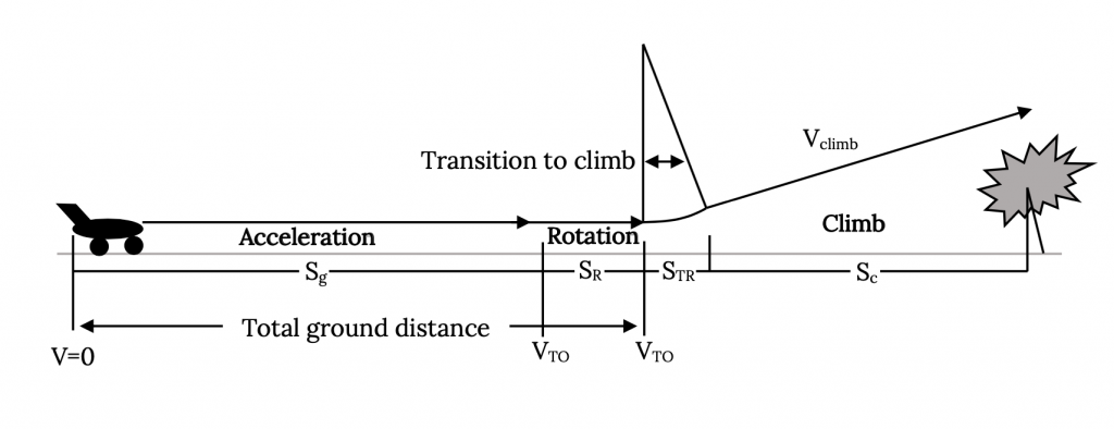
As discussed earlier, there are many components which may be included in the calculations of takeoff and landing distances. In the previous calculations only the actual ground run distances were considered and these, especially during landing, may be composed of multiple segments where different values of friction coefficient and thrust apply. A complete look at takeoff must also include the distance between the initiation of rotation and the establishment of a constant rate of climb and the distance needed to clear a defined obstacle height as shown in the figure below.
Several different terms may be used in a complete discussion of takeoff. These include the following:
Ground Roll: The distance from the start of the ground run or release of brakes until the point where the wheels leave the ground. This includes the distance needed to achieve the needed lift to equal the weight during rotation. The takeoff velocity must be at least 1.1 times the stall speed and is normally specified as between 1.1 and 1.2 times that speed.
Obstacle Clearance Distance: The distance between the point of brake release and that where a specified altitude is reached. This altitude is usually defined as 50 feet for military or smaller civil aviation aircraft and 35 feet for commercial aircraft.
Balanced Field Length: The length of the field required for safe completion of takeoff should one engine on a multi‑engine aircraft fail at the worst possible time during takeoff ground run. This distance includes the obstacle clearance distance. The balanced field length is sometimes also called the FAR Takeoff Field Length because it is a requirement for FAA certification in FAR 25 for commercial aircraft and includes the 35 foot obstacle clearance minimum. In the early part of the takeoff ground run the loss of one engine would usually lead to a decision to abort the takeoff, apply brakes and come to a stop. The “worst possible time” for engine failure would be when it is no longer possible to stop the aircraft before reaching the end of the runway and the decision must be made to continue the takeoff with one engine out.
Decision Speed (V1): The speed at which the distance to stop after the failure of one engine exactly equals the distance to continue takeoff on the remaining engines and to clear the FAA defined obstacles. In calculating this speed one cannot assume the possibility of using reverse thrust as part of the braking process.
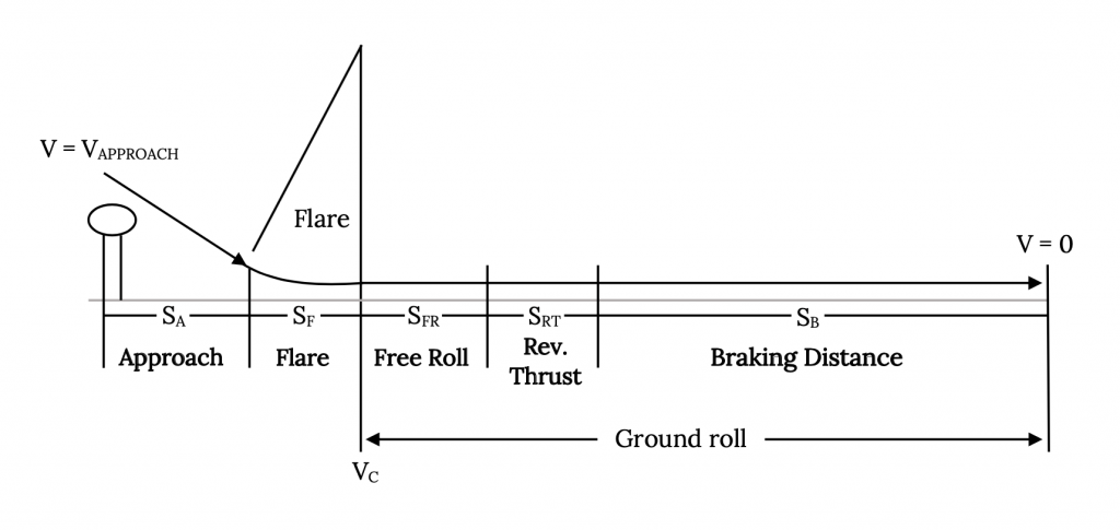
7.8.2 Landing
As in takeoff, landing includes several possible segments as shown in Figure 7.3. Our previous calculations included only the actual ground roll distance but a complete definition may also include the portion of the approach needed to clear a defined obstacle and that needed to transition from a steady approach glide to touchdown (the “flare distance”). Note that the landing ground run could also include portions with reversed thrust used alone or with the brakes.
The weight of the aircraft at landing is normally less than that at takeoff due to the use of fuel during the flight, however it is common to calculate the landing distance of trainer aircraft and of most propeller driven aircraft at takeoff weight. For non‑trainer jets, landing weight is normally assumed to be 85% of the takeoff weight. Military requirements usually assume landing with a full payload and about half of the fuel.
As in takeoff, there are several definitions associated with landing which should be familiar to the performance engineer:
FAR 23 Landing Field Length: This distance includes that needed to clear a 50 foot obstacle at approach speed flying down a defined approach glidepath (normally about 3 degrees). Touchdown is usually at about 1.15 times the stall speed. This total distance is usually about twice that of the calculated ground roll distance. This distance is normally about the same as that specified in requests for proposals for military aircraft.
FAR25 Landing Field Length: This distance adds to that of FAR 23 above an arbitrary two-thirds as a safety margin.
Homework 7
1. An aircraft has the following specifications:
W = 24,000 lb
S = 600 ft2
CD0 = 0.02
K = 0.056
This aircraft has run out of fuel at an altitude of 30,000 ft. Find the initial and final values of its airspeed for best range, the glide angle for best range, its rate of descent at this speed, and the time taken to descend to sea level at this speed.
2. For the aircraft above, assume a sea level thrust of 6,000 pounds and assume that thrust at altitude is equal to the sea level thrust times the density ratio (sigma). Find the true airspeeds for best rate of climb at sea level, at 20,000 ft, 30,000 ft and 40,000 ft. Also find the ceiling altitude.
3. For an aircraft where:
W = 10,000 lb
W/S = 50 psf
CD0 = 0.015
K = 0.02
Find the best rate of climb and the velocity for best rate of climb at sea level where T = constant = 4,000 lb and at an altitude of 40,000 ft where T = 2,000 lb.
References
Figure 7.1: Kindred Grey (2021). “Forces on an Aircraft in Take-off or Landing.” CC BY 4.0. Adapted from James F. Marchman (2004). CC BY 4.0. Available from https://archive.org/details/7.1-updated
Figure 7.2: Kindred Grey (2021). “Takeoff Segments.” CC BY 4.0. Adapted from James F. Marchman (2004). CC BY 4.0. Available from https://archive.org/details/7.2-updated
Figure 7.3: Kindred Grey (2021). “Landing Segments.” CC BY 4.0. Adapted from James F. Marchman (2004). CC BY 4.0. Available from https://archive.org/details/7.3-updated
<!– pb_fixme –><!– pb_fixme –>