16.8: Chapter 8- Atmospheric Rock Cutting
- Page ID
- 35240
16.8.1. Calc.: Cutting Forces & Mechanisms
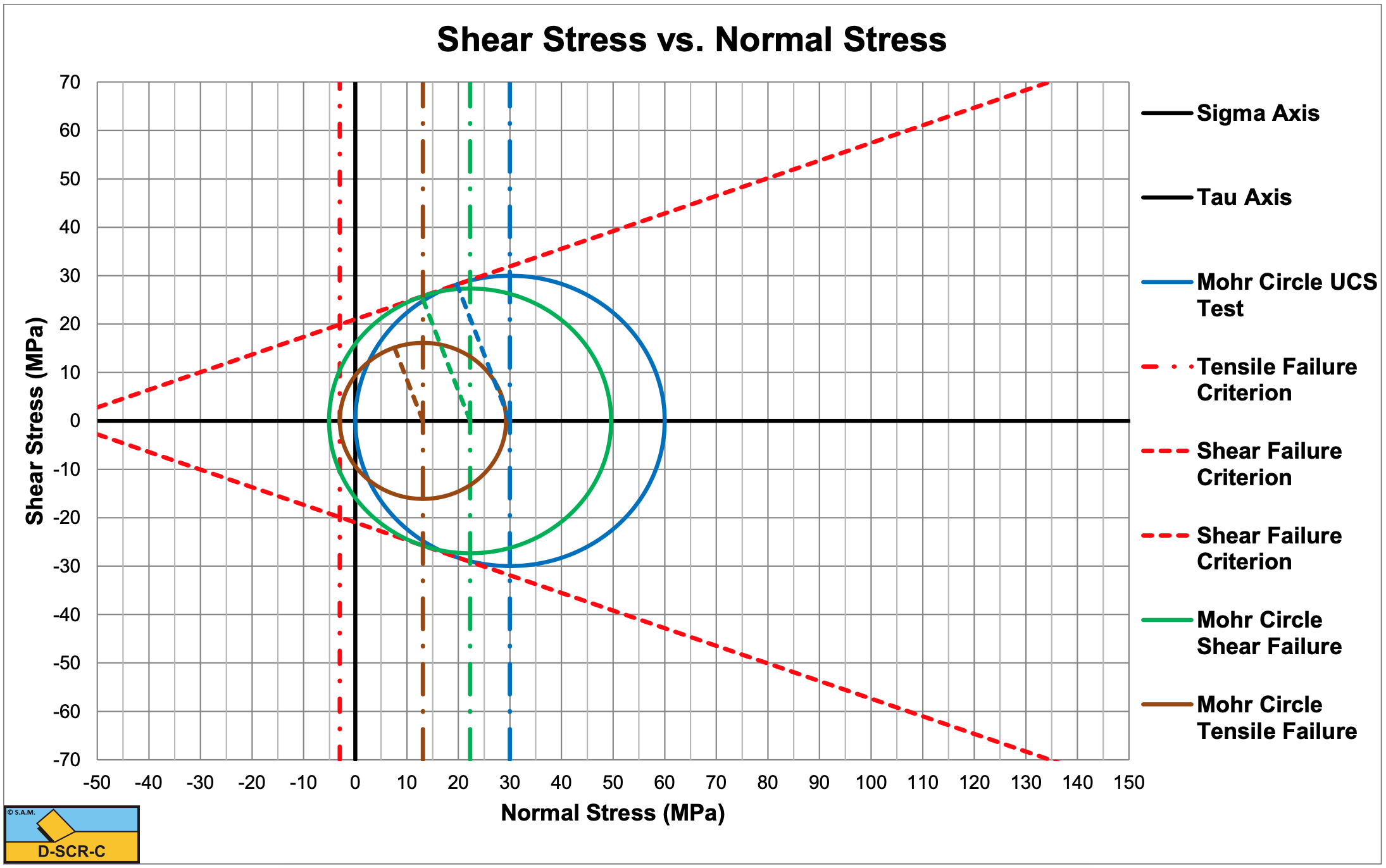
Consider a rock with a compressive strength of 30 MPa and a tensile strength of -2 MPa. The angle of internal friction is 18 degrees, the angle of external friction is 12 degrees. A blade angle of 55 degrees is used and a blade height of 0.2 m and blade width w=0.1 m. The layer thickness is 0.1 m.
Is the cutting process brittle shear or brittle tensile?
The cohesion or shear strength is:
\(\ \mathrm{c=\frac{U C S}{2} \cdot\left(\frac{1-\sin (\varphi)}{\cos (\varphi)}\right)=10.9 M P a}\)
According to Figure 8-38 (Figure 8.22, 1st edition) & (φ=18°), the BTS/Cohesion ratio should be above -0.3 for tensile failure, the ratio is -2/10.9=-0.183 which is above -0.3, so the process is brittle tensile failure.
If the tensile strength is -10 MPa, is the cutting process brittle shear or brittle tensile?
Now the ratio is -10/10.9=-0.92, which is below -0.3, so the process is shear failure, which is often related to ductile failure, but it is brittle shear failure.
What are the horizontal and the vertical cutting forces?
According to Figure 8-45 (Figure 8.28, 1st edition) the brittle horizontal coefficient λHT is about 3.07 and according to Figure 8-46 (Figure 8.29, 1st edition) the brittle vertical coefficient λVT about 1.30. This gives for a tensile strength of -2 MPa:
\(\ \mathrm{F}_{\mathrm{h}}=\lambda_{\mathrm{H T}} \cdot \sigma_{\mathrm{T}} \cdot \mathrm{h}_{\mathrm{i}} \cdot \mathrm{w}=\mathrm{3.0 7} \cdot \mathrm{2 0 0 0} \cdot \mathrm{0 .1} \cdot \mathrm{0 .1}=\mathrm{6 1} \mathrm{k N}\)
\(\ \mathrm{F}_{\mathrm{v}}=\lambda_{\mathrm{V T}} \cdot \sigma_{\mathrm{T}} \cdot \mathrm{h}_{\mathrm{i}} \cdot \mathrm{w}=\mathrm{1 .3 0} \cdot \mathrm{2 0 0 0} \cdot \mathrm{0 .1} \cdot \mathrm{0 .1}=\mathrm{2 6} \mathrm{k N}\)
For the case with a tensile strength of -10 MPa, the following is found:
According to Figure 8-31 (Figure 8.16, 1st edition) the brittle shear horizontal coefficient λHF is about 1.61 and according to Figure 8-32 (Figure 8.17, 1st edition) the brittle shear vertical coefficient λVF about 0.68. This gives for a compressive strength of 30 MPa (cohesion about 10.9 MPa):
\(\ \mathrm{F}_{\mathrm{h}}=\lambda_{\mathrm{HF}} \cdot \mathrm{c} \cdot \mathrm{h}_{\mathrm{i}} \cdot \mathrm{w}=\mathrm{1 .6 1} \cdot \mathrm{1 0 9 0 0} \cdot \mathrm{0 .1} \cdot \mathrm{0 .1}=\mathrm{17 6} \mathrm{k N}\)
\(\ \mathrm{F_{v}=\lambda_{V F} \cdot \mathrm{c} \cdot h_{i} \cdot \mathrm{w}=0.68 \cdot 10900 \cdot 0.1 \cdot 0.1=75 \mathrm{kN}}\)
16.8.2. Calc.: Cutting Forces & Mechanisms
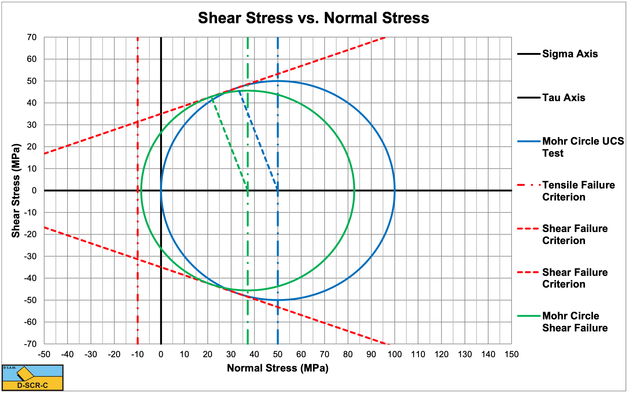
Consider a rock with a compressive strength of 100 MPa and a tensile strength of -10 MPa. The angle of internal friction is 20 degrees, the angle of external friction is 13.33 degrees. A blade angle of 60 degrees is used and a blade height of 0.1 m and blade width w=1 m. The layer thickness is 0.1 m.
The shear angle is:
\(\ \beta=\frac{\pi}{2}-\frac{\alpha+\delta+\varphi}{2}=43.33\text{ degrees}\)
The cohesion or shear strength is:
\(\ \mathrm{c=\frac{U C S}{2} \cdot\left(\frac{1-\sin (\varphi)}{\cos (\varphi)}\right)=35 M P a}\)
The normal stress on the shear plane is:
\(\ \sigma_{\mathrm{N} 1}=\frac{-\mathrm{c} \cdot \cos (\alpha+\beta+\delta)}{\sin (\alpha+\beta+\delta+\varphi)} \cdot \cos (\varphi)=21.52 \mathrm{M} \mathrm{Pa}\)
The shear stress on the shear plane is:
\(\ \tau_{\mathrm{S} 1}=\mathrm{c}+\sigma_{\mathrm{N} 1} \cdot \tan (\varphi)=42.84 \mathrm{M} \mathrm{P} \mathrm{a}\)
The normal stress in the center of the Mohr circle is:
\(\ \sigma_{\mathrm{C}}=\sigma_{\mathrm{N} 1}+\tau_{\mathrm{S} 1} \cdot \tan (\varphi)=37.1 \mathrm{M} \mathrm{P} \mathrm{a}\)
The radius of this Mohr circle is now:
\(\ \mathrm{R}=\frac{\tau_{\mathrm{S} 1}}{\cos (\varphi)}=45.59 \mathrm{M P a}\)
The minimum principle stress of this Mohr circle is:
\(\ \sigma_{\min }=\sigma_{\mathrm{C}}-\mathrm{R}=-\mathrm{8 .4 8} \mathrm{M P a}\)
Since -8.48 MPa>-10 MPa there is no tensile failure but shear failure.
The horizontal force is now:
\(\ \mathrm{F_{h}=\frac{2 \cdot c \cdot h_{i} \cdot w \cdot \cos (\varphi) \cdot \sin (\alpha+\delta)}{1+\cos (\alpha+\delta+\varphi)}=\lambda_{H F} \cdot c \cdot h_{i} \cdot w=1.912 \cdot 35 \cdot 0.1 \cdot 1=6.691 \ M N}\)
The vertical force is now:
\(\ \mathrm{F}_{v}=\frac{\mathrm{2} \cdot \mathrm{c} \cdot \mathrm{h}_{\mathrm{i}} \cdot \mathrm{w} \cdot \cos (\varphi) \cdot \cos (\alpha+\delta)}{\mathrm{1}+\cos (\alpha+\delta+\varphi)}=\lambda_{\mathrm{V F}} \cdot \mathrm{c} \cdot \mathrm{h}_{\mathrm{i}} \cdot \mathrm{w}=\mathrm{0 .5 7 2} \cdot \mathrm{3 5} \cdot \mathrm{0 .1} \cdot \mathrm{1}=\mathrm{2.0} \mathrm{\ M N}\)
16.8.3. Calc.: Cutting Forces & Mechanisms
Consider a rock with a compressive strength of 100 MPa and a tensile strength of -5 MPa. The angle of internal friction is 20 degrees, the angle of external friction is 13.33 degrees. A blade angle of 60 degrees is used and a blade height of 0.1 m and blade width w=1 m. The layer thickness is 0.1 m.
The shear angle is:
\(\ \beta=\frac{\pi}{2}-\frac{\alpha+\delta+\varphi}{2}=43.33\text{ degrees}\)
The cohesion or shear strength is:
\(\ \mathrm{c=\frac{U C S}{2} \cdot\left(\frac{1-\sin (\varphi)}{\cos (\varphi)}\right)=35 M P a}\)
The normal stress on the shear plane is:
\(\ \sigma_{\mathrm{N} 1}=\frac{-\mathrm{c} \cdot \cos (\alpha+\beta+\delta)}{\sin (\alpha+\beta+\delta+\varphi)} \cdot \cos (\varphi)=21.52 \text{ MPa}\)
The shear stress on the shear plane is:
\(\ \tau_{\mathrm{S} 1}=\mathrm{c}+\sigma_{\mathrm{N} 1} \cdot \tan (\varphi)=42.84 \text{ MPa}\)
The normal stress in the center of the Mohr circle is:
\(\ \sigma_{\mathrm{C}}=\sigma_{\mathrm{N} 1}+\tau_{\mathrm{S} 1} \cdot \tan (\varphi)=37.1 \text{ MPa}\)
The radius of this Mohr circle is now:
\(\ \mathrm{R}=\frac{\tau_{\mathrm{S} 1}}{\cos (\varphi)}=45.59 \text{ MPa}\)
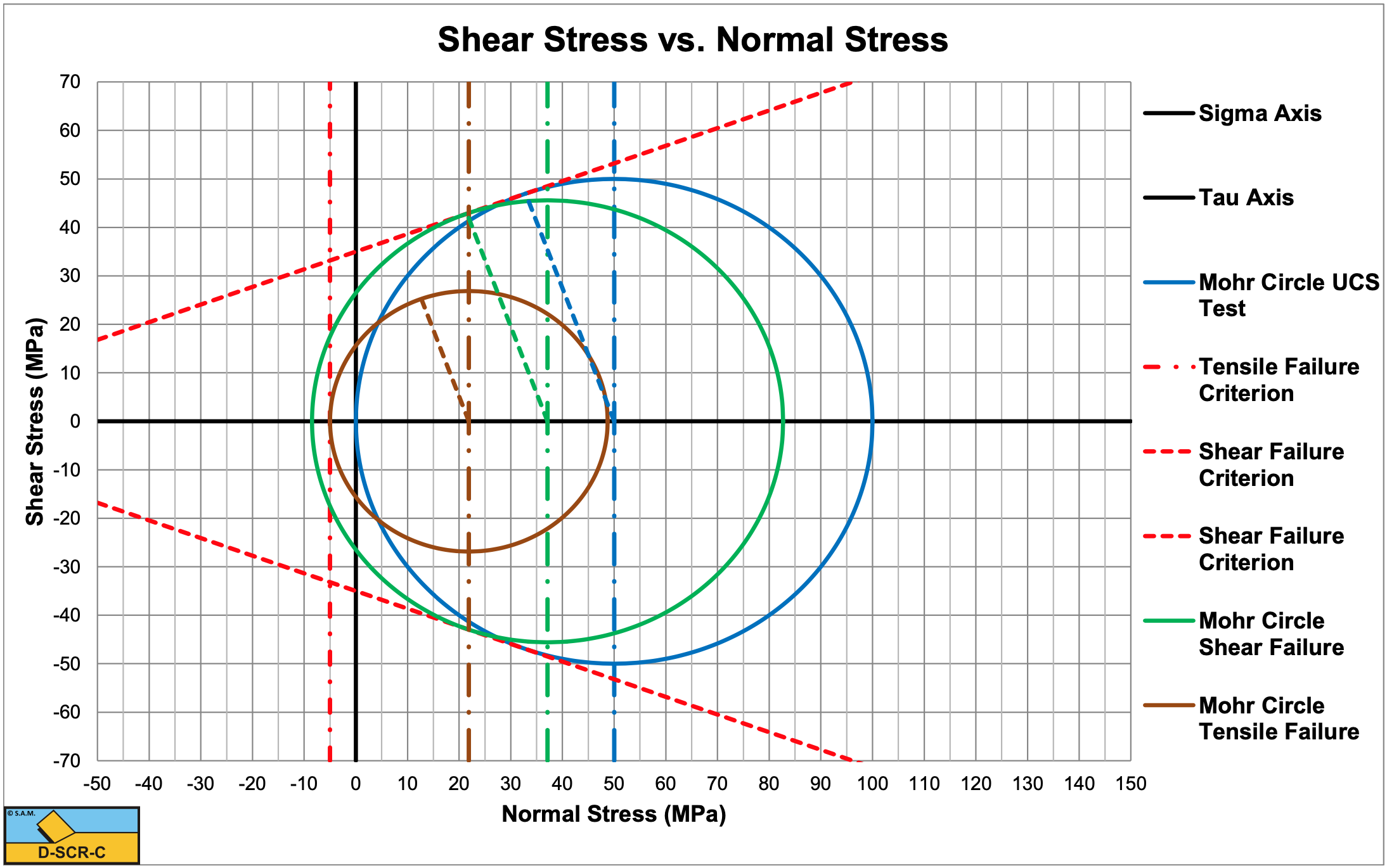
The minimum principle stress of this Mohr circle is:
\(\ \mathrm{\sigma_{\min }=\sigma_{\mathrm{C}}-R=-8.48 \text{ MPa}}\)
Since -8.48 MPa<-5 MPa there is tensile failure but no shear failure. This results in another shear angle of 25.8°.
The horizontal force is now, Figure 8-45 (Figure 8.28, 1st edition):
\(\ \mathrm{F_{h}=\frac{2 \cdot c_{m} \cdot h_{i} \cdot w \cdot \cos (\varphi) \cdot \sin (\alpha+\delta)}{1+\cos (\alpha+\delta+\varphi)}=\lambda_{H T} \cdot \sigma_{T} \cdot h_{i} \cdot w=4 \cdot 5 \cdot 0.1 \cdot 1=2} \text{ MN}\)
The vertical force is now, Figure 8-46 (Figure 8.29, 1st edition):
\(\ \mathrm{F}_{v}=\mathrm{\frac{2 \cdot c_{m} \cdot h_{i} \cdot w \cdot \cos (\varphi) \cdot \cos (\alpha+\delta)}{1+\cos (\alpha+\delta+\varphi)}=\lambda_{V T} \cdot \sigma_{T} \cdot h_{i} \cdot w=1.25 \cdot 5 \cdot 0.1 \cdot 1=0.625}\text{ MN}\)
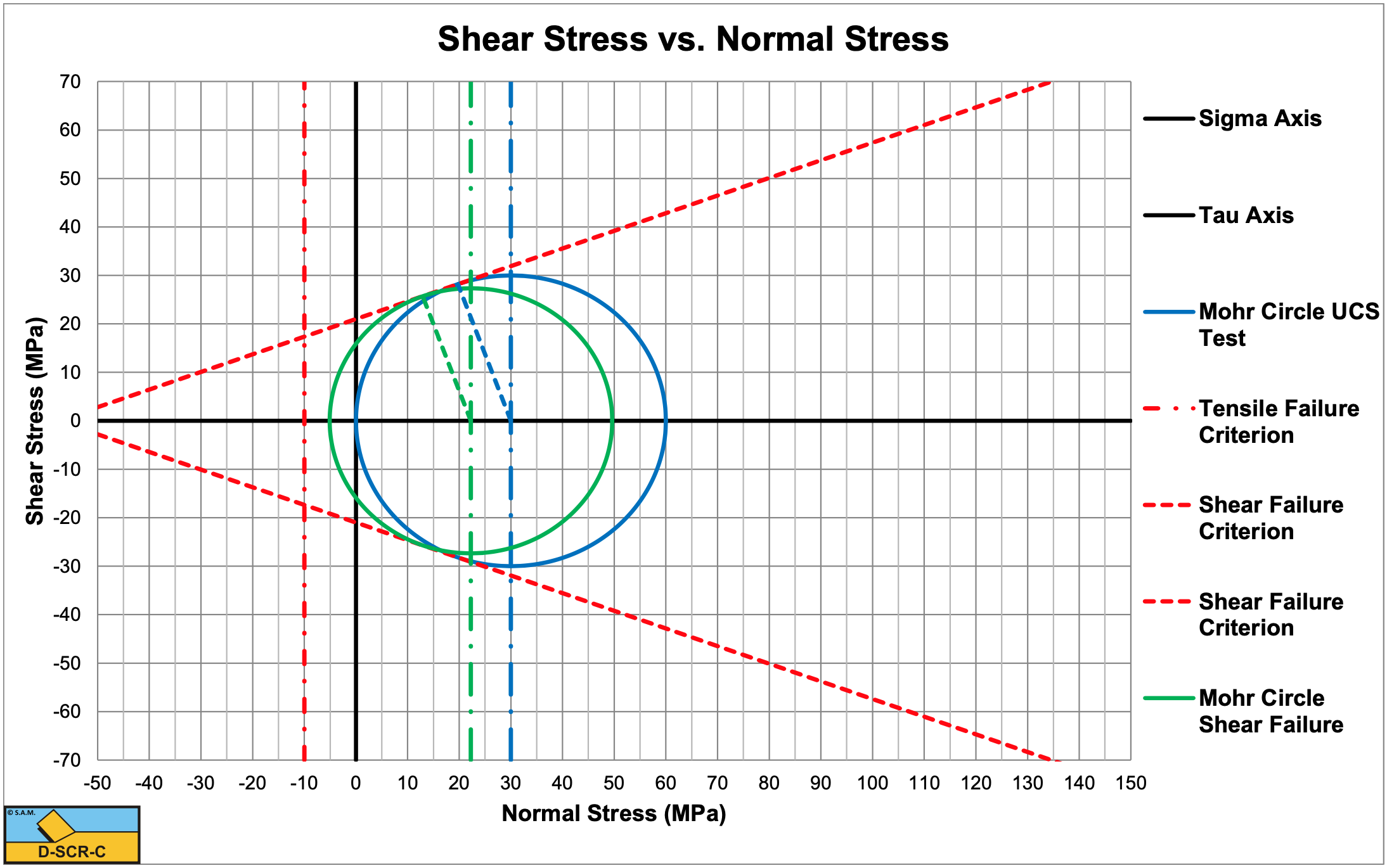
16.8.4. Calc.: Cutting Forces & Mechanisms
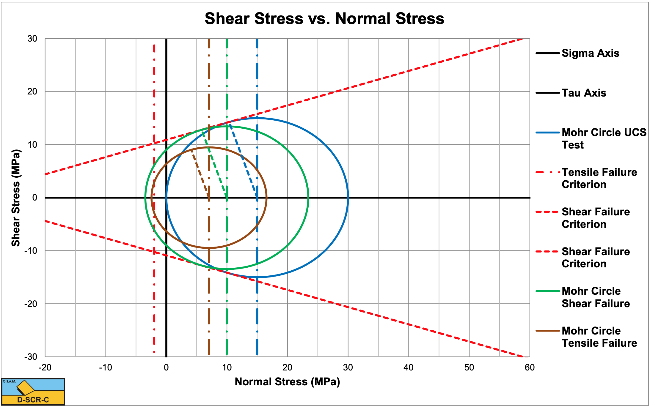
Consider a rock with a compressive strength of 60 MPa and a tensile strength of -10 MPa. The angle of internal friction is 20 degrees, the angle of external friction is 13.33 degrees. A blade angle of 60 degrees is used and a blade height of 0.1 m and blade width w=1 m. The layer thickness is 0.1 m.
The shear angle is:
\(\ \beta=\frac{\pi}{2}-\frac{\alpha+\delta+\varphi}{2}=43.33\text{ degree}\)
The cohesion or shear strength is:
\(\ \mathrm{c=\frac{U C S}{2} \cdot\left(\frac{1-\sin (\varphi)}{\cos (\varphi)}\right)=21}\text{ MPa}\)
The normal stress on the shear plane is:
\(\ \sigma_{\mathrm{N} 1}=\frac{-\mathrm{c} \cdot \cos (\alpha+\beta+\delta)}{\sin (\alpha+\beta+\delta+\varphi)} \cdot \cos (\varphi)=12.9 \text{ MPa}\)
The shear stress on the shear plane is:
\(\ \mathrm{\tau_{\mathrm{S} 1}=c+\sigma_{\mathrm{N} 1} \cdot \tan (\varphi)=25.7 \text{ MPa}}\)
The normal stress in the center of the Mohr circle is:
\(\ \sigma_{\mathrm{C}}=\sigma_{\mathrm{N} 1}+\tau_{\mathrm{S} 1} \cdot \tan (\varphi)=22.27 \text{ MPa}\)
The radius of this Mohr circle is now:
\(\ \mathrm{R}=\frac{\tau_{\mathrm{S} 1}}{\cos (\varphi)}=27.35 \text{ MPa}\)
The minimum principle stress of this Mohr circle is:
\(\ \sigma_{\min }=\sigma_{\mathrm{C}}-\mathrm{R}=-\mathrm{5.0 9} \text{ MPa}\)
Since -5.09 MPa>-10 MPa there is no tensile failure but shear failure.
The horizontal force is now:
\(\ \mathrm{F_{h}}=\mathrm{\frac{2 \cdot c \cdot h_{i} \cdot w \cdot \cos (\varphi) \cdot \sin (\alpha+\delta)}{1+\cos (\alpha+\delta+\varphi)}=\lambda_{H F} \cdot c \cdot h_{i} \cdot w=1.912 \cdot 21 \cdot 0.1 \cdot 1=4.02} \text{ MN}\)
The vertical force is now:
\(\ \mathrm{F}_{v}=\frac{\mathrm{2} \cdot \mathrm{c} \cdot \mathrm{h}_{\mathrm{i}} \cdot \mathrm{w} \cdot \cos (\varphi) \cdot \cos (\alpha+\delta)}{\mathrm{1}+\cos (\alpha+\delta+\varphi)}=\lambda_{\mathrm{V F}} \cdot \mathrm{c} \cdot \mathrm{h}_{\mathrm{i}} \cdot \mathrm{w}=\mathrm{0 .5 7 2} \cdot \mathrm{2 1} \cdot \mathrm{0 .1} \cdot \mathrm{1}=\mathrm{1 .2 0} \text{ MN}\)
16.8.5. Calc.: Cutting Forces & Mechanisms
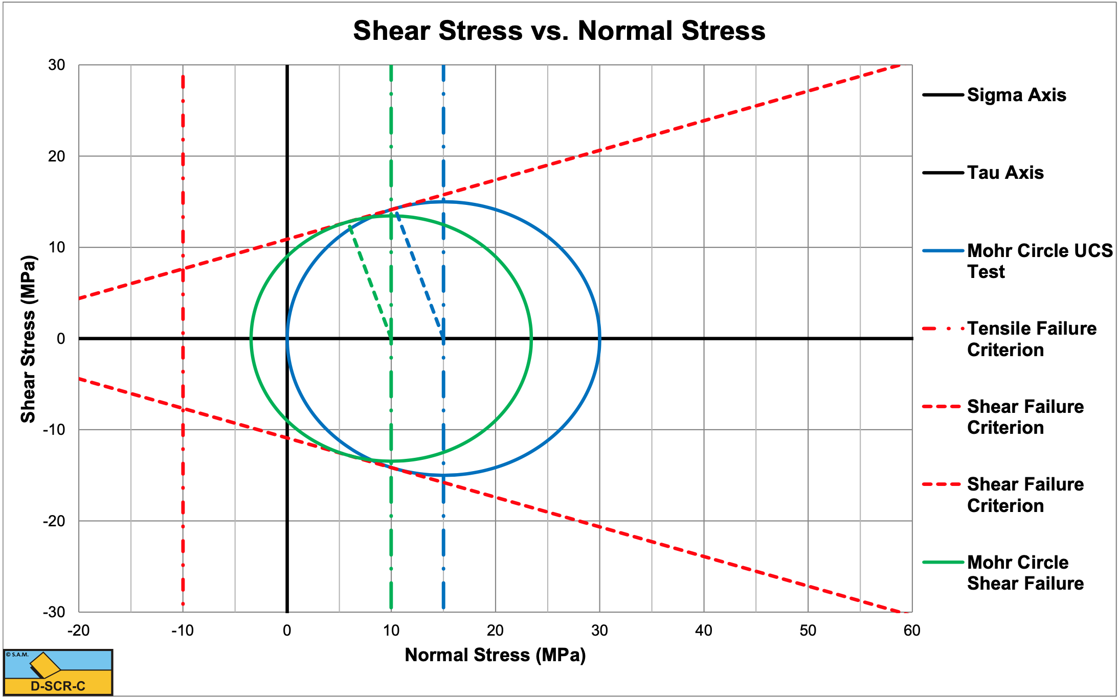
Consider a rock with a compressive strength of 60 MPa and a tensile strength of -3 MPa. The angle of internal friction is 20 degrees, the angle of external friction is 13.33 degrees. A blade angle of 60 degrees is used and a blade height of 0.1 m and blade width w=1 m. The layer thickness is 0.1 m.
The shear angle is:
\(\ \beta=\frac{\pi}{2}-\frac{\alpha+\delta+\varphi}{2}=43.33\text{ degrees}\)
The cohesion or shear strength is:
\(\ \mathrm{c=\frac{U C S}{2} \cdot\left(\frac{1-\sin (\varphi)}{\cos (\varphi)}\right)=21 \text{ MPa}}\)
The normal stress on the shear plane is:
\(\ \sigma_{\mathrm{N} 1}=\frac{-\mathrm{c} \cdot \cos (\alpha+\beta+\delta)}{\sin (\alpha+\beta+\delta+\varphi)} \cdot \cos (\varphi)=12.9 \text{ MPa}\)
The shear stress on the shear plane is:
\(\ \tau_{\mathrm{S} 1}=\mathrm{c}+\sigma_{\mathrm{N} 1} \cdot \tan (\varphi)=25.7 \text{ MPa}\)
The normal stress in the center of the Mohr circle is:
\(\ \sigma_{\mathrm{C}}=\sigma_{\mathrm{N} 1}+\tau_{\mathrm{S} 1} \cdot \tan (\varphi)=22.27 \text{ MPa}\)
The radius of this Mohr circle is now:
\(\ \mathrm{R}=\frac{\tau_{\mathrm{S} 1}}{\cos (\varphi)}=27.35 \text{ MPa}\)
The minimum principle stress of this Mohr circle is:
\(\ \sigma_{\min }=\sigma_{\mathrm{C}}-\mathrm{R}=-5.09 \text{ MPa}\)
Since -5.09 MPa<-3 MPa there is tensile failure but no shear failure. This results in another shear angle of 25.8°.
The horizontal force is now, Figure 8-45 (Figure 8.28, 1st edition):
\(\ \mathrm{F_{h}=\frac{2 \cdot c_{m} \cdot h_{i} \cdot w \cdot \cos (\varphi) \cdot \sin (\alpha+\delta)}{1+\cos (\alpha+\delta+\varphi)}=\lambda_{H T} \cdot \sigma_{T} \cdot h_{i} \cdot w=4.1 \cdot 3 \cdot 0.1 \cdot 1=1.24} \text{ MN}\)
The vertical force is now, Figure 8-46 (Figure 8.29, 1st edition):
\(\ \mathrm{F}_{v}=\mathrm{\frac{2 \cdot c_{m} \cdot h_{i} \cdot w \cdot \cos (\varphi) \cdot \cos (\alpha+\delta)}{1+\cos (\alpha+\delta+\varphi)}=\lambda_{V T} \cdot \sigma_{T} \cdot h_{i} \cdot w=1.24 \cdot 3 \cdot 0.1 \cdot 1=0.371} \text{ MN}\)