
5.2: Assembler
- Page ID
- 19884

The assembler(For more information, refer to: http://en.Wikipedia.org/wiki/Assembl...ing)#Assembler) is a program that will read an assembly language input file and convert the code into a machine language binary file. The input file is an assembly language source file containing assembly language instructions in human readable form. The machine language output is referred to as an object file. As part of this process, the comments are removed, and the variable names and labels are converted into appropriate addresses (as required by the CPU during execution).
The assembler used in this text is the yasm(For more information, refer to: https://en.Wikipedia.org/wiki/Yasm) assembler. Links to the yasm web site and documentation can be found in Chapter 1, Introduction
Assemble Commands
The appropriate yasm assembler command for reading the assembly language source file, such as the example from the previous chapter, is as follows:
yasm -g dwarf2 -f elf64 example.asm -l example.lst
Note, the -l is a dash lower-case letter L (which is easily confused with the number 1).
The -g dwarf2(For more information, refer to: https://en.Wikipedia.org/wiki/DWARF) option is used to inform the assembler to include debugging information in the final object file. This increases the size of the object file, but is necessary to allow effective debugging. The -f elf64 informs the assembler to create the object file in the ELF64(For more information, refer to: http://en.Wikipedia.org/wiki/Executa...inkable_Format) format which is appropriate for 64-bit, Linux-based systems. The example.asm is the name of the assembly language source file for input. The -l example.lst (dash lower-case letter L) informs the assembler to create a list file named example.lst.
If an error occurs during the assembly process, it must be resolved before continuing to the link step.
File
In addition, the assembler is optionally capable of creating a list file. The list file shows the line number, the relative address, the machine language version of the instruction (including variable references), and the original source line. The list file can be useful when debugging.
For example, a fragment from the list file data section, from the example program in the previous chapter is as follows:
36 00000009 40660301        dVar1    dd  17000000
37 0000000D 40548900        dVar2    dd  9000000
38 00000011 00000000        dResult  dd  0
On the first line, the 36 is the line number. The next number, 0x00000009, is the relative address in the data area of where that variable will be stored. Since dVar1 is a double-word, which requires four bytes, the address for the next variable is 0x0000000D. The dVar1 variable uses 4 bytes as addresses 0x00000009, 0x0000000A, 0x0000000B, and 0x0000000C. The rest of the line is the data declaration as typed in the original assembly language source file.
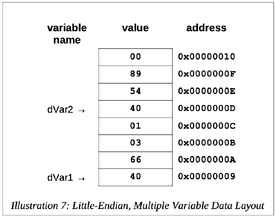
The 0x40660301 is the value, in hex, as placed in memory. The \(17,000,000_{10}\) is 0x01036640. Recalling that the architecture is little-endian, the least significant byte (0x40) is placed in the lowest memory address. As such, the 0x40 is placed in relative address 0x00000009, the next byte, 0x66, is placed in address 0x0000000A and so forth. This can be confusing as at first glance the number may appear backwards or garbled (depending on how it is viewed).
To help visualize, the memory picture would be as follows:
For example, a fragment of the list file text section, excerpted from the example program in the previous chapter is as follows:
95                            last:
96 0000005A 48C7C03C000000        mov        rax, SYS_exit
97 00000061 48C7C300000000        mov        rdi, EXIT_SUCCESS
98 00000068 0F05                  syscall
Again, the numbers to the left are the line numbers. The next number, 0x0000005A, is the relative address of where the line of code will be placed.
The next number, 0x48C7C03C000000, is the machine language version of the instruction, in hex, that the CPU reads and understands. The rest of the line is the original assembly language source instruction.
The label, last:, does not have a machine language instruction since the label is used to reference a specific address and is not an executable instruction.
Two-Pass Assembler
The assembler(For more information, refer to: http://en.Wikipedia.org/wiki/Assembl...uage#Assembler) will read the source file and convert each assembly language instruction, typed by the programmer, into a set of 1's and 0's that the CPU knows to be that instruction. The 1's and 0's are referred to as machine language. There is a one-to- one correspondence between the assembly language instructions and the binary machine language. This relationship means that machine language, in the form of an executable file can be converted back into human readable assembly language. Of course, the comments, variable names, and label names are missing, so the resulting code can be very difficult to read.
As the assembler reads each line of assembly language, it generates machine code for that instruction. This will work well for instructions that do not perform jumps. However, for instructions that might change the control flow (e.g., IF statements, unconditional jumps), the assembler is not able to convert the instruction. For example, given the following code fragment:
    mov        rax, 0
    jmp        skipRest
    ...
    ...
    skipRest:
This is referred to as a forward reference. If the assembler reads the assembly file one line at a time, it has not read the line where skipRest is defined. In fact, it does not even know for sure if skipRest is defined at all.
This situation can be resolved by reading the assembly source file twice. The entire
process is referred to as a two-pass assembler. The steps required for each pass are detailed in the following sections.
First Pass
The steps taken on the first pass vary based on the design of the specific assembler. However, some of the basic operations performed on the first pass include the following:
- Create symbol table
- Expand macros
- Evaluate constant expressions
A macro is a program element that is expanded into a set of programmer predefined instructions. For more information, refer to Chapter 11, Macros.
A constant expression is an expression composed entirely of constants. Since the expression is constants only, it can be fully evaluated at assemble-time. For example, assuming the constant BUFF is defined, the following instruction contains a constant expression;
mov rax, BUFF+5
This type of constant expression is used commonly in large or complex programs.
Addresses are assigned to all statements in the program. The symbol table is a listing or table of all the program symbols, variable names and program labels, and their respective addresses in the program.
As appropriate, some assembler directives are processed in the first pass.
Second Pass
The steps taken on the second pass vary based on the design of the specific assembler. However, some of the basic operations performed on the second pass include the following:
- Final generation of code
- Creation of list file (if requested)
- Create object file
The term code generation refers to the conversion of the programmer provided assembly language instruction into the CPU executable machine language instruction. Due to the one-to-one correspondence, this can be done for instructions that do not use symbols on either the first or second pass.
It should be noted that, based on the assembler design, much of the code generation might be done on the first pass or all done on the second pass. Either way, the final generation is performed on the second pass. This will require using the symbol table to check program symbols and obtain the appropriate addresses from the table.
The list file, while optional, can be useful for debugging. If requested, it would be generated on the second pass.
If there are no errors, the final object file is created on the second pass.
Assembler Directives
Assembler directives are instructions to the assembler that direct the assembler to do something. This might be formatting or layout. These directives are not translated into instructions for the CPU.