6.5: Solar Cells
- Page ID
- 18976
\( \newcommand{\vecs}[1]{\overset { \scriptstyle \rightharpoonup} {\mathbf{#1}} } \)
\( \newcommand{\vecd}[1]{\overset{-\!-\!\rightharpoonup}{\vphantom{a}\smash {#1}}} \)
\( \newcommand{\dsum}{\displaystyle\sum\limits} \)
\( \newcommand{\dint}{\displaystyle\int\limits} \)
\( \newcommand{\dlim}{\displaystyle\lim\limits} \)
\( \newcommand{\id}{\mathrm{id}}\) \( \newcommand{\Span}{\mathrm{span}}\)
( \newcommand{\kernel}{\mathrm{null}\,}\) \( \newcommand{\range}{\mathrm{range}\,}\)
\( \newcommand{\RealPart}{\mathrm{Re}}\) \( \newcommand{\ImaginaryPart}{\mathrm{Im}}\)
\( \newcommand{\Argument}{\mathrm{Arg}}\) \( \newcommand{\norm}[1]{\| #1 \|}\)
\( \newcommand{\inner}[2]{\langle #1, #2 \rangle}\)
\( \newcommand{\Span}{\mathrm{span}}\)
\( \newcommand{\id}{\mathrm{id}}\)
\( \newcommand{\Span}{\mathrm{span}}\)
\( \newcommand{\kernel}{\mathrm{null}\,}\)
\( \newcommand{\range}{\mathrm{range}\,}\)
\( \newcommand{\RealPart}{\mathrm{Re}}\)
\( \newcommand{\ImaginaryPart}{\mathrm{Im}}\)
\( \newcommand{\Argument}{\mathrm{Arg}}\)
\( \newcommand{\norm}[1]{\| #1 \|}\)
\( \newcommand{\inner}[2]{\langle #1, #2 \rangle}\)
\( \newcommand{\Span}{\mathrm{span}}\) \( \newcommand{\AA}{\unicode[.8,0]{x212B}}\)
\( \newcommand{\vectorA}[1]{\vec{#1}} % arrow\)
\( \newcommand{\vectorAt}[1]{\vec{\text{#1}}} % arrow\)
\( \newcommand{\vectorB}[1]{\overset { \scriptstyle \rightharpoonup} {\mathbf{#1}} } \)
\( \newcommand{\vectorC}[1]{\textbf{#1}} \)
\( \newcommand{\vectorD}[1]{\overrightarrow{#1}} \)
\( \newcommand{\vectorDt}[1]{\overrightarrow{\text{#1}}} \)
\( \newcommand{\vectE}[1]{\overset{-\!-\!\rightharpoonup}{\vphantom{a}\smash{\mathbf {#1}}}} \)
\( \newcommand{\vecs}[1]{\overset { \scriptstyle \rightharpoonup} {\mathbf{#1}} } \)
\(\newcommand{\longvect}{\overrightarrow}\)
\( \newcommand{\vecd}[1]{\overset{-\!-\!\rightharpoonup}{\vphantom{a}\smash {#1}}} \)
\(\newcommand{\avec}{\mathbf a}\) \(\newcommand{\bvec}{\mathbf b}\) \(\newcommand{\cvec}{\mathbf c}\) \(\newcommand{\dvec}{\mathbf d}\) \(\newcommand{\dtil}{\widetilde{\mathbf d}}\) \(\newcommand{\evec}{\mathbf e}\) \(\newcommand{\fvec}{\mathbf f}\) \(\newcommand{\nvec}{\mathbf n}\) \(\newcommand{\pvec}{\mathbf p}\) \(\newcommand{\qvec}{\mathbf q}\) \(\newcommand{\svec}{\mathbf s}\) \(\newcommand{\tvec}{\mathbf t}\) \(\newcommand{\uvec}{\mathbf u}\) \(\newcommand{\vvec}{\mathbf v}\) \(\newcommand{\wvec}{\mathbf w}\) \(\newcommand{\xvec}{\mathbf x}\) \(\newcommand{\yvec}{\mathbf y}\) \(\newcommand{\zvec}{\mathbf z}\) \(\newcommand{\rvec}{\mathbf r}\) \(\newcommand{\mvec}{\mathbf m}\) \(\newcommand{\zerovec}{\mathbf 0}\) \(\newcommand{\onevec}{\mathbf 1}\) \(\newcommand{\real}{\mathbb R}\) \(\newcommand{\twovec}[2]{\left[\begin{array}{r}#1 \\ #2 \end{array}\right]}\) \(\newcommand{\ctwovec}[2]{\left[\begin{array}{c}#1 \\ #2 \end{array}\right]}\) \(\newcommand{\threevec}[3]{\left[\begin{array}{r}#1 \\ #2 \\ #3 \end{array}\right]}\) \(\newcommand{\cthreevec}[3]{\left[\begin{array}{c}#1 \\ #2 \\ #3 \end{array}\right]}\) \(\newcommand{\fourvec}[4]{\left[\begin{array}{r}#1 \\ #2 \\ #3 \\ #4 \end{array}\right]}\) \(\newcommand{\cfourvec}[4]{\left[\begin{array}{c}#1 \\ #2 \\ #3 \\ #4 \end{array}\right]}\) \(\newcommand{\fivevec}[5]{\left[\begin{array}{r}#1 \\ #2 \\ #3 \\ #4 \\ #5 \\ \end{array}\right]}\) \(\newcommand{\cfivevec}[5]{\left[\begin{array}{c}#1 \\ #2 \\ #3 \\ #4 \\ #5 \\ \end{array}\right]}\) \(\newcommand{\mattwo}[4]{\left[\begin{array}{rr}#1 \amp #2 \\ #3 \amp #4 \\ \end{array}\right]}\) \(\newcommand{\laspan}[1]{\text{Span}\{#1\}}\) \(\newcommand{\bcal}{\cal B}\) \(\newcommand{\ccal}{\cal C}\) \(\newcommand{\scal}{\cal S}\) \(\newcommand{\wcal}{\cal W}\) \(\newcommand{\ecal}{\cal E}\) \(\newcommand{\coords}[2]{\left\{#1\right\}_{#2}}\) \(\newcommand{\gray}[1]{\color{gray}{#1}}\) \(\newcommand{\lgray}[1]{\color{lightgray}{#1}}\) \(\newcommand{\rank}{\operatorname{rank}}\) \(\newcommand{\row}{\text{Row}}\) \(\newcommand{\col}{\text{Col}}\) \(\renewcommand{\row}{\text{Row}}\) \(\newcommand{\nul}{\text{Nul}}\) \(\newcommand{\var}{\text{Var}}\) \(\newcommand{\corr}{\text{corr}}\) \(\newcommand{\len}[1]{\left|#1\right|}\) \(\newcommand{\bbar}{\overline{\bvec}}\) \(\newcommand{\bhat}{\widehat{\bvec}}\) \(\newcommand{\bperp}{\bvec^\perp}\) \(\newcommand{\xhat}{\widehat{\xvec}}\) \(\newcommand{\vhat}{\widehat{\vvec}}\) \(\newcommand{\uhat}{\widehat{\uvec}}\) \(\newcommand{\what}{\widehat{\wvec}}\) \(\newcommand{\Sighat}{\widehat{\Sigma}}\) \(\newcommand{\lt}{<}\) \(\newcommand{\gt}{>}\) \(\newcommand{\amp}{&}\) \(\definecolor{fillinmathshade}{gray}{0.9}\)Solar Cell Efficiency
Energy conversion devices are never 100% efficient. Efficiency is defined as the output power over the input power. Efficiency of a solar cell is often defined as the ratio of electrical power out to optical power in to the device.
\[\eta_{ef \, f} = \frac{P_{electrical \; out}}{P_{optical \; in}} \nonumber \]
Not all sunlight reaches a solar cell because some of it is absorbed by the earth's atmosphere. This atmospheric absorption is strongly dependent on wavelength. Figure 6.4.5 is a plot of the transmissivity of the atmosphere as a function of wavelength. It plots the percent of light which passes through the atmosphere without getting absorbed. Some gases in the atmosphere, such as water vapor and \(\text{CO}_2\), absorb a significant amount of energy at particular wavelengths. The figure indicates which gas is responsible for atmospheric absorption at some particular wavelengths. For example, ozone \(\text{O}_3\) absorbs ultraviolet light. Ozone in the atmosphere offers benefits because ultraviolet light can damage eyes and skin. The intensity of the optical power from the sun that is hits a solar cell varies from day to day and location to location. In a bright sunny area, a solar cell may receive around \(0.1 \frac{W}{cm^2}\) [73, p. 7].
Even if energy from the sunlight reaches a solar cell, the energy is not converted to electricity with perfect efficiency. There are multiple reasons for this inefficiency, and some of these reasons relate to the fact that not all light that hits a solar cell is absorbed. Light may heat up the solar cell instead of exciting electrons to create electron-hole pairs [74]. Alternatively, light may be reflected off the solar cell surface [74]. Many solar cells have an antireflection coating to reduce reflections, but they are not eliminated. The surface of other solar cells are manufactured to be rough instead of smooth to reduce reflections. Furthermore, if a photon hits an electron that is already excited, the photon will not be absorbed. Additionally, solar cells have wires throughout the surface to capture the produced electricity. These wires are often thin and in a finger-like configuration. Light that hits these wires does not reach the semiconductor portion of the solar cell and is not efficiently converted to electricity. To reduce this issue, wires of some solar cells are made from materials that are partially transparent conductors, such as indium tin oxide or tin oxide \(\text{SnO}_2\) [74]. Indium tin oxide is a transparent conductor with a moderately high electrical conductivity of \(\sigma = 10^6 \frac{1} {\Omega \cdot m}\) [75].
Other reasons that solar cells are not perfectly efficient have to do with what happens after a photon excites an electron. An electron may be excited, but it may decay before it gets swept from the junction [74]. A photon may excite an electron to a level above the conduction band, but the electron may quickly decay to the top of the conduction band losing some energy to heat. Internal resistance in the bulk n-type or p-type regions may convert electricity to heat. There may also be internal resistance of wiring in the system. Also unmatched loads make solar cells less efficient than matched loads [74].
The voltage across and the current produced by an illuminated solar cell are both functions of temperature. Reference [76] demonstrates, both theoretically and experimentally, that efficiency of a solar cell decreases as temperature increases. A number of mechanisms occurring in a solar cell are dependent on temperature. First, as the temperature increases, the allowed energy levels broaden. For this reason, the energy gap \(E_g\), which is proportional to the voltage produced by the solar cell, is smaller at higher temperatures. As temperature increases, this voltage produced by the solar cell decreases roughly linearly [76]. Second, the current due to recombination of electron-hole pairs at the junction is a function of temperature. At higher temperatures, more electron-hole pairs recombine at the junction, so the overall current produced by the solar cell is less. For this reason, as temperature increases, the overall current produced by the solar cell decreases roughly exponentially [76]. This eect on the current is the main reason that solar cell efficiency depends on temperature. Other mechanisms are temperature dependent, but are less significant [76].
Solar Cell Technologies
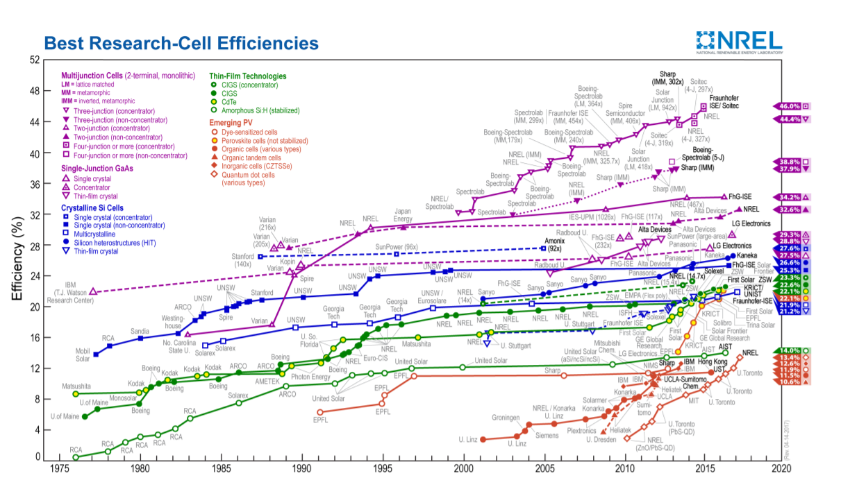
There are four major solar cell technologies being developed: crystalline, thin film, multijunction cells, and emerging photovoltaic technologies [77]. However, these categories are not distinct because some solar cells fit into multiple categories simultaneously. Figure \(\PageIndex{1}\), from [77], compares solar cells of these technologies. More specifically, it shows record efficiencies for each of these types of solar cells as well as the year the records were achieved.
The first category is crystalline, and these cells may be made from single crystals or from polycrystalline material [78]. The first generation of solar cells was made with this technology. For a simple recipe for how to produce a crystalline solar cell, see [69]. Most solar cells produced today, around 80% of the market, are silicon cells in this category. Typical efficiency of a crystalline solar cell available today may be around 20% [78]. Polycrystalline solar cells are often cheaper and a bit less efficient than single crystalline cells.
The second category is thin film. To make these solar cells, thin films of semiconductors are deposited on a substrate such as glass or steel. The substrate may be rigid or flexible. The solar cell itself may be made of layers of material only a few microns thick. Thin film solar cells may be cheaper than other types of solar cells [78]. Often they are less efficient than crystalline cells, but they have other advantages [78]. One material used to make thin film solar cells is amorphous silicon. Another material in use is CdTe, which has a energy gap 1.45 eV. Cadmium and tellurium are both toxic, but they may be easier to deposit in thin films than silicon.
The third category is multijunction, also called compound, solar cells. These solar cells are made of a dozen or more layers of semiconductor stacked on top of each other [78]. These layers form multiple pn junctions. Larger gap semiconductors are on the upper layers, and smaller gap semiconductors are closer to the substrate. These solar cells can be quite efficient. Cells with efficiency up to 46% have been demonstrated in labs [77].
The last category is emerging technology solar cells. Multiple creative strategies are being used to develop solar cells. Nanotechnology strategies include using solar cells made from carbon nanotubes and from quantum dot based materials [78]. Organic solar cells also fall into this category. The active part of these solar cells is a thin, often 100-200 nm, layer of an organic material [79]. One advantage of organic solar cells is that their processing may not require as high of temperatures as the processing of solar cells made from pn junctions of inorganic semiconductors [79].
Solar Cell Systems
Solar cells are used in a wide range of devices. Inexpensive lawn ornaments with solar cells are available at hardware stores for less than a dollar. Small photovoltaic devices used as optical sensors are equally inexpensive. On the other extreme, solar cells power the NASA Mars rovers Spirit and Opportunity as well as satellites orbiting the earth. Also, large arrays of solar cells are used to generate electricity.
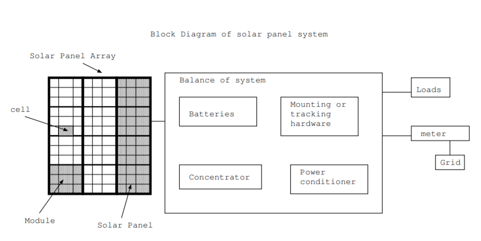
A typical solar cell produces around a watt of electrical power while a typical house may require around 4 kW of power [73]. To produce the necessary power, individual solar cells are connected together into modules, and the modules are connected together into solar panels. In a typical installation on the roof of a house, a panel may be composed of around 40 solar cells, and 10 or 20 panels may be mounted roof [73]. A typical solar panel installation on the roof of a building has a number of components in addition to the solar panel arrays. The additional components are often referred to as the balance of the system, and they consist of batteries, mounting or tracking hardware, solar concentrators, and power conditioners. These components are illustrated in Fig. \(\PageIndex{2}\).
The mounting system is composed of the foundation, mechanical supports, brackets, and wiring needed to physically mount and connect the solar panel. Some solar panels are mounted in a fixed position. Other solar panels are mounted on systems that angle the panels towards the sun. Some tracking systems rotate the panel around a single east-west axis. Others have two axes. Two axis tracking systems are often used with solar concentrators. A concentrator is a mirror or lens system designed to capture more of the sun's light onto the panels.
Solar panel systems require batteries or some other energy storage mechanism to provide electrical power at night, on cloudy days, and other times when inadequate sunlight falls on the solar panels. Solar panels can last 30 years or more with only about 1% or 2% degradation per year. Also, solar panels rarely need maintenance, and they cannot easily be repaired. If a solar panel fails, the entire panel is replaced. However, batteries have a typical lifetime of three to nine years, and they are often the first part of a solar panel system that needs replacement [73].


The power conditioning system consists of an inverter which converts DC electricity to AC and, for grid tied systems, a system to match the phase of the produced AC power to the phase of the grid. Power conditioning systems also contain a system to limit the current or voltage to maximize the power delivered. Also, they include safeguards such as fuses to prevent injury or damage to equipment. The typical lifetime for the electronics may be around 10-15 years [73].


