
12.4: Current Rating and Resistance
- Page ID
- 57691
\( \newcommand{\vecs}[1]{\overset { \scriptstyle \rightharpoonup} {\mathbf{#1}} } \)
\( \newcommand{\vecd}[1]{\overset{-\!-\!\rightharpoonup}{\vphantom{a}\smash {#1}}} \)
\( \newcommand{\dsum}{\displaystyle\sum\limits} \)
\( \newcommand{\dint}{\displaystyle\int\limits} \)
\( \newcommand{\dlim}{\displaystyle\lim\limits} \)
\( \newcommand{\id}{\mathrm{id}}\) \( \newcommand{\Span}{\mathrm{span}}\)
( \newcommand{\kernel}{\mathrm{null}\,}\) \( \newcommand{\range}{\mathrm{range}\,}\)
\( \newcommand{\RealPart}{\mathrm{Re}}\) \( \newcommand{\ImaginaryPart}{\mathrm{Im}}\)
\( \newcommand{\Argument}{\mathrm{Arg}}\) \( \newcommand{\norm}[1]{\| #1 \|}\)
\( \newcommand{\inner}[2]{\langle #1, #2 \rangle}\)
\( \newcommand{\Span}{\mathrm{span}}\)
\( \newcommand{\id}{\mathrm{id}}\)
\( \newcommand{\Span}{\mathrm{span}}\)
\( \newcommand{\kernel}{\mathrm{null}\,}\)
\( \newcommand{\range}{\mathrm{range}\,}\)
\( \newcommand{\RealPart}{\mathrm{Re}}\)
\( \newcommand{\ImaginaryPart}{\mathrm{Im}}\)
\( \newcommand{\Argument}{\mathrm{Arg}}\)
\( \newcommand{\norm}[1]{\| #1 \|}\)
\( \newcommand{\inner}[2]{\langle #1, #2 \rangle}\)
\( \newcommand{\Span}{\mathrm{span}}\) \( \newcommand{\AA}{\unicode[.8,0]{x212B}}\)
\( \newcommand{\vectorA}[1]{\vec{#1}} % arrow\)
\( \newcommand{\vectorAt}[1]{\vec{\text{#1}}} % arrow\)
\( \newcommand{\vectorB}[1]{\overset { \scriptstyle \rightharpoonup} {\mathbf{#1}} } \)
\( \newcommand{\vectorC}[1]{\textbf{#1}} \)
\( \newcommand{\vectorD}[1]{\overrightarrow{#1}} \)
\( \newcommand{\vectorDt}[1]{\overrightarrow{\text{#1}}} \)
\( \newcommand{\vectE}[1]{\overset{-\!-\!\rightharpoonup}{\vphantom{a}\smash{\mathbf {#1}}}} \)
\( \newcommand{\vecs}[1]{\overset { \scriptstyle \rightharpoonup} {\mathbf{#1}} } \)
\(\newcommand{\longvect}{\overrightarrow}\)
\( \newcommand{\vecd}[1]{\overset{-\!-\!\rightharpoonup}{\vphantom{a}\smash {#1}}} \)
\(\newcommand{\avec}{\mathbf a}\) \(\newcommand{\bvec}{\mathbf b}\) \(\newcommand{\cvec}{\mathbf c}\) \(\newcommand{\dvec}{\mathbf d}\) \(\newcommand{\dtil}{\widetilde{\mathbf d}}\) \(\newcommand{\evec}{\mathbf e}\) \(\newcommand{\fvec}{\mathbf f}\) \(\newcommand{\nvec}{\mathbf n}\) \(\newcommand{\pvec}{\mathbf p}\) \(\newcommand{\qvec}{\mathbf q}\) \(\newcommand{\svec}{\mathbf s}\) \(\newcommand{\tvec}{\mathbf t}\) \(\newcommand{\uvec}{\mathbf u}\) \(\newcommand{\vvec}{\mathbf v}\) \(\newcommand{\wvec}{\mathbf w}\) \(\newcommand{\xvec}{\mathbf x}\) \(\newcommand{\yvec}{\mathbf y}\) \(\newcommand{\zvec}{\mathbf z}\) \(\newcommand{\rvec}{\mathbf r}\) \(\newcommand{\mvec}{\mathbf m}\) \(\newcommand{\zerovec}{\mathbf 0}\) \(\newcommand{\onevec}{\mathbf 1}\) \(\newcommand{\real}{\mathbb R}\) \(\newcommand{\twovec}[2]{\left[\begin{array}{r}#1 \\ #2 \end{array}\right]}\) \(\newcommand{\ctwovec}[2]{\left[\begin{array}{c}#1 \\ #2 \end{array}\right]}\) \(\newcommand{\threevec}[3]{\left[\begin{array}{r}#1 \\ #2 \\ #3 \end{array}\right]}\) \(\newcommand{\cthreevec}[3]{\left[\begin{array}{c}#1 \\ #2 \\ #3 \end{array}\right]}\) \(\newcommand{\fourvec}[4]{\left[\begin{array}{r}#1 \\ #2 \\ #3 \\ #4 \end{array}\right]}\) \(\newcommand{\cfourvec}[4]{\left[\begin{array}{c}#1 \\ #2 \\ #3 \\ #4 \end{array}\right]}\) \(\newcommand{\fivevec}[5]{\left[\begin{array}{r}#1 \\ #2 \\ #3 \\ #4 \\ #5 \\ \end{array}\right]}\) \(\newcommand{\cfivevec}[5]{\left[\begin{array}{c}#1 \\ #2 \\ #3 \\ #4 \\ #5 \\ \end{array}\right]}\) \(\newcommand{\mattwo}[4]{\left[\begin{array}{rr}#1 \amp #2 \\ #3 \amp #4 \\ \end{array}\right]}\) \(\newcommand{\laspan}[1]{\text{Span}\{#1\}}\) \(\newcommand{\bcal}{\cal B}\) \(\newcommand{\ccal}{\cal C}\) \(\newcommand{\scal}{\cal S}\) \(\newcommand{\wcal}{\cal W}\) \(\newcommand{\ecal}{\cal E}\) \(\newcommand{\coords}[2]{\left\{#1\right\}_{#2}}\) \(\newcommand{\gray}[1]{\color{gray}{#1}}\) \(\newcommand{\lgray}[1]{\color{lightgray}{#1}}\) \(\newcommand{\rank}{\operatorname{rank}}\) \(\newcommand{\row}{\text{Row}}\) \(\newcommand{\col}{\text{Col}}\) \(\renewcommand{\row}{\text{Row}}\) \(\newcommand{\nul}{\text{Nul}}\) \(\newcommand{\var}{\text{Var}}\) \(\newcommand{\corr}{\text{corr}}\) \(\newcommand{\len}[1]{\left|#1\right|}\) \(\newcommand{\bbar}{\overline{\bvec}}\) \(\newcommand{\bhat}{\widehat{\bvec}}\) \(\newcommand{\bperp}{\bvec^\perp}\) \(\newcommand{\xhat}{\widehat{\xvec}}\) \(\newcommand{\vhat}{\widehat{\vvec}}\) \(\newcommand{\uhat}{\widehat{\uvec}}\) \(\newcommand{\what}{\widehat{\wvec}}\) \(\newcommand{\Sighat}{\widehat{\Sigma}}\) \(\newcommand{\lt}{<}\) \(\newcommand{\gt}{>}\) \(\newcommand{\amp}{&}\) \(\definecolor{fillinmathshade}{gray}{0.9}\)The last part of machine rating is its current capability. This is heavily influenced by cooling methods, for the principal limit on current is the heating produced by resistive dissipation. Generally, it is possible to do first-order design estimates by assuming a current density that can be handled by a particular cooling scheme. Then, in an air-gap winding:
\(\ N_{a} I_{a}=\left(R_{w o}^{2}-R_{w i}^{2}\right) \frac{\theta_{w e}}{2} J_{a}\)
and note that, usually, the armature fills the azimuthal space in the machine:
\(\ 2 q \theta_{w e}=2 \pi\)
For a winding in slots, nearly the same thing is true: if the rectangular slot model holds true:
\(\ 2 q N_{a} I_{a}=N_{s} h_{s} w_{s} J_{s}\)
where we are using \(\ J_{s}\) to note slot current density. Now, suppose we can characterize the total slot area by a “space factor” \(\ \lambda_{s}\) which is the ratio between total slot area and the annulus occupied by the slots: for the rectangular slot model:
\(\ \lambda_{s}=\frac{N_{s} h_{s} w_{s}}{\pi\left(R_{w o}^{2}-R_{w i}^{2}\right)}\)
where \(\ R_{w i}=R+h_{d}\) and \(\ R_{w o}=R_{w i}+h_{s}\) in a normal, stator outside winding. In this case, \(\ J_{a}=J_{s} \lambda_{s}\) and the two types of machines can be evaluated in the same way.
It would seem apparent that one would want to make \(\ \lambda_{s}\) as large as possible, to permit high currents. The limit on this is that the magnetic teeth between the conductors must be able to carry the air-gap flux, and making them too narrow would cause them to saturate. The peak of the time fundamental magnetic field in the teeth is, for example,
\(\ B_{t}=B_{1} \frac{2 \pi R}{N_{s} w_{t}}\)
where \(\ w_{t}\) is the width of a stator tooth:
\(\ w_{t}=\frac{2 \pi\left(R+h_{d}\right)}{N_{s}}-w_{s}\)
so that
\(\ B_{t} \approx \frac{B_{1}}{1-\lambda_{s}}\)
Resistance
Winding resistance may be estimated as the length of the stator conductor divided by its area and its conductivity. The length of the stator conductor is:
\(\ l_{c}=2 l N_{a} f_{e}\)
where the “end winding factor” \(\ f_{e}\) is used to take into account the extra length of the end turns (which is usually not negligible). The area of each turn of wire is, for an air-gap winding:
\(\ A_{w}=\frac{\theta_{w e}}{2} \frac{R_{w o}^{2}-R_{w i}^{2}}{N_{a}} \lambda_{w}\)
where \(\ \lambda_{w}\), the “packing factor” relates the area of conductor to the total area of the winding. The resistance is then just:
\(\ R_{a}=\frac{4 l N_{a}^{2}}{\theta_{w e}\left(R_{w o}^{2}-R_{w i}^{2}\right) \lambda_{w} \sigma}\)
and, of course, \(\ \sigma\) is the conductivity of the conductor.
For windings in slots the expression is almost the same, simply substituting the total slot area:
\(\ R_{a}=\frac{2 q l N_{a}^{2}}{N_{s} h_{s} w_{s} \lambda_{w} \sigma}\)
The end turn allowance depends strongly on how the machine is made. One way of estimating what it might be is to assume that the end turns follow a roughly circular path from one side of the machine to the other. The radius of this circle would be, very roughly, \(\ R_{w} / p\), where is the average radius of the winding: \(\ R_{w} \approx\left(R_{w o}+R_{w i}\right) / 2\)
Then the end-turn allowance would be:
\(\ f_{e}=1+\frac{\pi R_{w}}{p l}\)
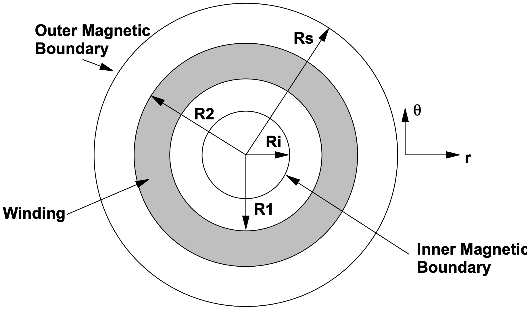 Figure 10: Coordinate System for Inductance Calculation