
8.5: Exercises
- Page ID
- 25290

\( \newcommand{\vecs}[1]{\overset { \scriptstyle \rightharpoonup} {\mathbf{#1}} } \)
\( \newcommand{\vecd}[1]{\overset{-\!-\!\rightharpoonup}{\vphantom{a}\smash {#1}}} \)
\( \newcommand{\id}{\mathrm{id}}\) \( \newcommand{\Span}{\mathrm{span}}\)
( \newcommand{\kernel}{\mathrm{null}\,}\) \( \newcommand{\range}{\mathrm{range}\,}\)
\( \newcommand{\RealPart}{\mathrm{Re}}\) \( \newcommand{\ImaginaryPart}{\mathrm{Im}}\)
\( \newcommand{\Argument}{\mathrm{Arg}}\) \( \newcommand{\norm}[1]{\| #1 \|}\)
\( \newcommand{\inner}[2]{\langle #1, #2 \rangle}\)
\( \newcommand{\Span}{\mathrm{span}}\)
\( \newcommand{\id}{\mathrm{id}}\)
\( \newcommand{\Span}{\mathrm{span}}\)
\( \newcommand{\kernel}{\mathrm{null}\,}\)
\( \newcommand{\range}{\mathrm{range}\,}\)
\( \newcommand{\RealPart}{\mathrm{Re}}\)
\( \newcommand{\ImaginaryPart}{\mathrm{Im}}\)
\( \newcommand{\Argument}{\mathrm{Arg}}\)
\( \newcommand{\norm}[1]{\| #1 \|}\)
\( \newcommand{\inner}[2]{\langle #1, #2 \rangle}\)
\( \newcommand{\Span}{\mathrm{span}}\) \( \newcommand{\AA}{\unicode[.8,0]{x212B}}\)
\( \newcommand{\vectorA}[1]{\vec{#1}} % arrow\)
\( \newcommand{\vectorAt}[1]{\vec{\text{#1}}} % arrow\)
\( \newcommand{\vectorB}[1]{\overset { \scriptstyle \rightharpoonup} {\mathbf{#1}} } \)
\( \newcommand{\vectorC}[1]{\textbf{#1}} \)
\( \newcommand{\vectorD}[1]{\overrightarrow{#1}} \)
\( \newcommand{\vectorDt}[1]{\overrightarrow{\text{#1}}} \)
\( \newcommand{\vectE}[1]{\overset{-\!-\!\rightharpoonup}{\vphantom{a}\smash{\mathbf {#1}}}} \)
\( \newcommand{\vecs}[1]{\overset { \scriptstyle \rightharpoonup} {\mathbf{#1}} } \)
\( \newcommand{\vecd}[1]{\overset{-\!-\!\rightharpoonup}{\vphantom{a}\smash {#1}}} \)
\(\newcommand{\avec}{\mathbf a}\) \(\newcommand{\bvec}{\mathbf b}\) \(\newcommand{\cvec}{\mathbf c}\) \(\newcommand{\dvec}{\mathbf d}\) \(\newcommand{\dtil}{\widetilde{\mathbf d}}\) \(\newcommand{\evec}{\mathbf e}\) \(\newcommand{\fvec}{\mathbf f}\) \(\newcommand{\nvec}{\mathbf n}\) \(\newcommand{\pvec}{\mathbf p}\) \(\newcommand{\qvec}{\mathbf q}\) \(\newcommand{\svec}{\mathbf s}\) \(\newcommand{\tvec}{\mathbf t}\) \(\newcommand{\uvec}{\mathbf u}\) \(\newcommand{\vvec}{\mathbf v}\) \(\newcommand{\wvec}{\mathbf w}\) \(\newcommand{\xvec}{\mathbf x}\) \(\newcommand{\yvec}{\mathbf y}\) \(\newcommand{\zvec}{\mathbf z}\) \(\newcommand{\rvec}{\mathbf r}\) \(\newcommand{\mvec}{\mathbf m}\) \(\newcommand{\zerovec}{\mathbf 0}\) \(\newcommand{\onevec}{\mathbf 1}\) \(\newcommand{\real}{\mathbb R}\) \(\newcommand{\twovec}[2]{\left[\begin{array}{r}#1 \\ #2 \end{array}\right]}\) \(\newcommand{\ctwovec}[2]{\left[\begin{array}{c}#1 \\ #2 \end{array}\right]}\) \(\newcommand{\threevec}[3]{\left[\begin{array}{r}#1 \\ #2 \\ #3 \end{array}\right]}\) \(\newcommand{\cthreevec}[3]{\left[\begin{array}{c}#1 \\ #2 \\ #3 \end{array}\right]}\) \(\newcommand{\fourvec}[4]{\left[\begin{array}{r}#1 \\ #2 \\ #3 \\ #4 \end{array}\right]}\) \(\newcommand{\cfourvec}[4]{\left[\begin{array}{c}#1 \\ #2 \\ #3 \\ #4 \end{array}\right]}\) \(\newcommand{\fivevec}[5]{\left[\begin{array}{r}#1 \\ #2 \\ #3 \\ #4 \\ #5 \\ \end{array}\right]}\) \(\newcommand{\cfivevec}[5]{\left[\begin{array}{c}#1 \\ #2 \\ #3 \\ #4 \\ #5 \\ \end{array}\right]}\) \(\newcommand{\mattwo}[4]{\left[\begin{array}{rr}#1 \amp #2 \\ #3 \amp #4 \\ \end{array}\right]}\) \(\newcommand{\laspan}[1]{\text{Span}\{#1\}}\) \(\newcommand{\bcal}{\cal B}\) \(\newcommand{\ccal}{\cal C}\) \(\newcommand{\scal}{\cal S}\) \(\newcommand{\wcal}{\cal W}\) \(\newcommand{\ecal}{\cal E}\) \(\newcommand{\coords}[2]{\left\{#1\right\}_{#2}}\) \(\newcommand{\gray}[1]{\color{gray}{#1}}\) \(\newcommand{\lgray}[1]{\color{lightgray}{#1}}\) \(\newcommand{\rank}{\operatorname{rank}}\) \(\newcommand{\row}{\text{Row}}\) \(\newcommand{\col}{\text{Col}}\) \(\renewcommand{\row}{\text{Row}}\) \(\newcommand{\nul}{\text{Nul}}\) \(\newcommand{\var}{\text{Var}}\) \(\newcommand{\corr}{\text{corr}}\) \(\newcommand{\len}[1]{\left|#1\right|}\) \(\newcommand{\bbar}{\overline{\bvec}}\) \(\newcommand{\bhat}{\widehat{\bvec}}\) \(\newcommand{\bperp}{\bvec^\perp}\) \(\newcommand{\xhat}{\widehat{\xvec}}\) \(\newcommand{\vhat}{\widehat{\vvec}}\) \(\newcommand{\uhat}{\widehat{\uvec}}\) \(\newcommand{\what}{\widehat{\wvec}}\) \(\newcommand{\Sighat}{\widehat{\Sigma}}\) \(\newcommand{\lt}{<}\) \(\newcommand{\gt}{>}\) \(\newcommand{\amp}{&}\) \(\definecolor{fillinmathshade}{gray}{0.9}\)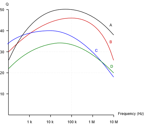
Inductor \(Q\) curves to be used with the exercises below
Analysis
1. A circuit has a resonant frequency of 440 kHz and a system \(Q\) of 30. Determine the bandwidth and the approximate values for \(f_1\) and \(f_2\).
2. A circuit has a resonant frequency of 19 kHz and a bandwidth of 500 Hz. Determine the system \(Q\) and the approximate values for \(f_1\) and \(f_2\).
3. Find the \(Q_{coil}\) and coil resistance of a 150 \(\mu\)H inductor at 100 kHz using device curve A.
4. Find the \(Q_{coil}\) and coil resistance of a 2.2 mH inductor at 50 kHz using device curve D.
5. At a certain frequency, an inductor's impedance is \(24 + j600\) \(\Omega\). Determine the parallel resistance and reactance that produces the same value.
6. At a certain frequency, an inductor's impedance is \(3 + j150\) \(\Omega\). Determine the parallel resistance and reactance that produces the same value.
7. A certain 75 \(\mu\)H inductor is described by curve B. Determine the equivalent parallel inductor/resistor combination at 1 MHz.
8. A certain 3.3 mH inductor is described by curve C. Determine the equivalent parallel inductor/resistor combination at 20 kHz.
9. Consider a series circuit consisting of a 2 nF capacitor, an ideal 33 \(\mu\)H inductor and a 5 \(\Omega\) resistor. Determine the resonant frequency, system \(Q\), and bandwidth.
10. Consider a series circuit consisting of a 20 nF capacitor, an ideal 100 \(\mu\)H inductor and a 2.7 \(\Omega\) resistor. Determine the resonant frequency, system \(Q\), and bandwidth.
11. Consider a series circuit consisting of a 50 nF capacitor, a 20 mH inductor with \(Q_{coil}\) of 50 and a 63 \(\Omega\) resistor. Determine the resonant frequency, system \(Q\), and bandwidth.
12. Consider a series circuit consisting of a 200 nF capacitor, a 1 mH inductor with \(Q_{coil}\) of 65 and a 72 \(\Omega\) resistor. Determine the resonant frequency, system \(Q\), and bandwidth.
13. For the circuit shown in Figure \(\PageIndex{1}\), determine the resonant frequency, system \(Q\) and bandwidth. Assume \(R_{coil} = 0\) \(\Omega\). If the source is 1 volt peak, determine the capacitor voltage at resonance.
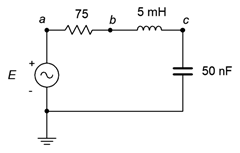
Figure \(\PageIndex{1}\)
14. For the circuit shown in Figure \(\PageIndex{2}\), determine the resonant frequency, system \(Q\) and bandwidth. Assume \(R_{coil} = 0\) \(\Omega\). If the source is 10 volts, determine the capacitor voltage at resonance.
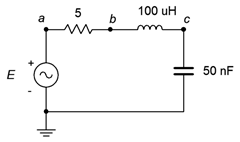
Figure \(\PageIndex{2}\)
15. Repeat problem 13 but assume instead that the inductor's \(R_{coil} = 15\) \(\Omega\).
16. Repeat problem 12 but assume instead that the inductor follows curve D.
17. For the circuit shown in Figure \(\PageIndex{3}\), determine the resonant frequency, system \(Q\) and bandwidth. If the source is 20 mA peak, determine the resistor and capacitor voltages at resonance.
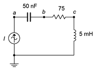
Figure \(\PageIndex{3}\)
18. For the circuit shown in Figure \(\PageIndex{4}\), determine the resonant frequency, system \(Q\) and bandwidth. If the source is 100 mA, determine the resistor and capacitor voltages at resonance.
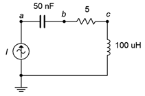
Figure \(\PageIndex{4}\)
19. For the circuit shown in Figure \(\PageIndex{5}\), determine the resonant frequency, system \(Q\) and bandwidth. If the source is 15 volts, determine the inductor and capacitor currents at resonance. Assume the inductor's coil resistance is 3.2 \(\Omega\).
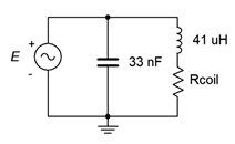
Figure \(\PageIndex{5}\)
20. For the circuit shown in Figure \(\PageIndex{6}\), determine the resonant frequency, system \(Q\) and bandwidth. If the source is 3 volts, determine the inductor and capacitor currents at resonance. Assume the inductor's \(Q\) is 30.
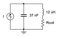
Figure \(\PageIndex{6}\)
21. For the circuit shown in Figure \(\PageIndex{7}\), determine the resonant frequency, system \(Q\) and bandwidth. If the source is 15 volts, determine the resistor, inductor and capacitor currents at resonance.
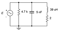
Figure \(\PageIndex{7}\)
22. Given the circuit shown in Figure \(\PageIndex{8}\), determine the resonant frequency, system \(Q\) and bandwidth. If the source is 2 volts, determine the resistor, inductor and capacitor currents at resonance. Assume the inductor's coil resistance is 2.5 \(\Omega\).
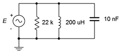
Figure \(\PageIndex{8}\)
23. For the circuit shown in Figure \(\PageIndex{9}\), determine the resonant frequency, system \(Q\) and bandwidth. If the source is 5 volts, determine the resistor, inductor and capacitor currents at resonance. Assume the inductor's \(Q\) is 40.
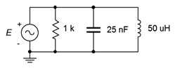
Figure \(\PageIndex{9}\)
24. Given the circuit shown in Figure \(\PageIndex{10}\), determine the resonant frequency, system \(Q\) and bandwidth. If the source is 2.5 mA, determine the resistor voltage and the three branch currents at resonance.
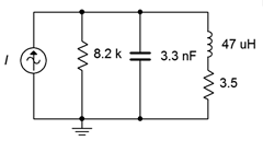
Figure \(\PageIndex{10}\)
25. For the circuit shown in Figure \(\PageIndex{11}\), determine the resonant frequency, system \(Q\) and bandwidth. If the source is 500 \(\mu\)A, determine the resistor voltage and the three branch currents at resonance. Assume the inductor's \(Q\) is given by curve C.
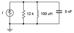
Figure \(\PageIndex{11}\)
26. Given the circuit shown in Figure \(\PageIndex{12}\), determine the resonant frequency, system \(Q\) and bandwidth. If the source is 10 mA, determine the resistor voltage and the three branch currents at resonance. Assume the inductor's \(Q\) is given by curve B.
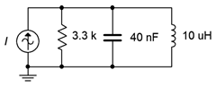
Figure \(\PageIndex{12}\)
Design
27. A series resonant circuit has a required \(f_0\) of 50 kHz. If a 75 nF capacitor is used, determine the required inductance.
28. A series resonant circuit has a required \(f_0\) of 210 kHz. If a 22 \(\mu\)H inductor is used, determine the required capacitance.
29. A parallel resonant circuit consists of a 12 nF capacitor and a 27 \(\mu\)H inductor with a \(Q_{coil}\) of 55. Determine the required additional parallel resistance to achieve a system \(Q\) of 40.
30. A series resonant circuit has a design target of \(f_0=200\) kHz with a bandwidth of 5 kHz. Which of the inductor curves above (A, B, C, D) represent possible candidates, if any, and why/why not?
31. A parallel resonant circuit has a design target of \(f_0=1\) MHz with a bandwidth of 20 kHz. Which of the inductor curves above (A, B, C, D) represent possible candidates, if any, and why/why not?
Challenge
32. A parallel resonant circuit has a required \(f_0\) of 50 kHz and a bandwidth of 4 kHz. If a 75 nF capacitor is used and the load impedance is 100 k\(\Omega\), determine the required inductance and minimum acceptable \(Q_{coil}\).
33. A parallel resonant circuit consists of a 150 nF capacitor and a 200 \(\mu\)H inductor that has a coil resistance of 1 \(\Omega\). The desired bandwidth for the network is 2 kHz. Determine the value of resistance to be placed in parallel with the network in order to achieve this goal.
34. A resonant circuit consists of a 4 nF capacitor in parallel with a 100 \(\mu\)H coil that has a coil resistance of 5 \(\Omega\). Determine the resonant frequency and bandwidth. Further, assume that this circuit is now loaded by an amplifier that has an input impedance equivalent to 10 k\(\Omega\) resistive in parallel with 500 pF of input capacitance. Also, the amplifier is connected via 25 feet of coaxial cable that exhibits a capacitance of 33 pF per foot. Determine the changes in resonant frequency and bandwidth, if any, with this load.
Simulation
35. Use an AC frequency domain analysis to verify the results of problem 13. Plot the resistor voltage from 0.1 \(f_0\) to 10 \(f_0\).
36. Use an AC frequency domain analysis to verify the results of problem 19. Do this by overlapping plots of the resistor, capacitor and inductor voltages across a range of 0.1 \(f_0\) to 10 \(f_0\).
37. Investigate the effects of inductor \(Q\) on the system bandwidth of problem 21. Plot the system voltage from 0.01 \(f_0\) to 100 \(f_0\) three times, the first using the specified coil resistance and then using values ten times larger and ten times smaller.
38. Investigate the effects of component tolerance on the system frequency response of problem 21. Plot the system voltage from 0.1 \(f_0\) to 10 \(f_0\) using a Monte Carlo variation on the AC frequency domain response. Set a 10% tolerance on the capacitor, inductor and resistor but do not alter the coil resistance.
39. Use an AC frequency domain analysis to verify the design of problem 27. Plot the resistor voltage from 0.1 \(f_0\) to 10 \(f_0\).
40. Use an AC frequency domain analysis to verify the design of problem 29. Plot the system voltage from 0.1 \(f_0\) to 10 \(f_0\).
41. At high \(Q\) values (>10) the capacitor and inductor voltages of series resonant circuits will tend to reach maximum very close to the resonant frequency. At lower \(Q\)s, these peaks tend to diverge. A similar situation occurs with the currents in parallel resonant circuits. Investigate this effect by performing an AC frequency domain analysis on problem 14. Overlay plots of \(v_{ab}\), \(v_{bc}\) and \(v_c\) for successively larger values of resistance.
42. Investigate the “\(Q\) increase” in reactive currents compared to source and resistive currents in a parallel resonant circuit. A simple way to verify this is by placing AC ammeters in each of the branches of the circuit shown in Figure \(\PageIndex{13}\). Use \(R\) = 630 \(\Omega\), \(C\) = 40 nF, \(L\) = 10 \(\mu\)H and \(i\) = 1 mA. It is worthwhile to compare sets of simulations for different resistor values to see the current changes relative to the system \(Q\). Slight variations of the source frequency may be required to reach the peak.
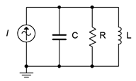
Figure \(\PageIndex{13}\)