
7.3: 2-to-4 Decoder Implementation
- Page ID
- 26990

\( \newcommand{\vecs}[1]{\overset { \scriptstyle \rightharpoonup} {\mathbf{#1}} } \) \( \newcommand{\vecd}[1]{\overset{-\!-\!\rightharpoonup}{\vphantom{a}\smash {#1}}} \)\(\newcommand{\id}{\mathrm{id}}\) \( \newcommand{\Span}{\mathrm{span}}\) \( \newcommand{\kernel}{\mathrm{null}\,}\) \( \newcommand{\range}{\mathrm{range}\,}\) \( \newcommand{\RealPart}{\mathrm{Re}}\) \( \newcommand{\ImaginaryPart}{\mathrm{Im}}\) \( \newcommand{\Argument}{\mathrm{Arg}}\) \( \newcommand{\norm}[1]{\| #1 \|}\) \( \newcommand{\inner}[2]{\langle #1, #2 \rangle}\) \( \newcommand{\Span}{\mathrm{span}}\) \(\newcommand{\id}{\mathrm{id}}\) \( \newcommand{\Span}{\mathrm{span}}\) \( \newcommand{\kernel}{\mathrm{null}\,}\) \( \newcommand{\range}{\mathrm{range}\,}\) \( \newcommand{\RealPart}{\mathrm{Re}}\) \( \newcommand{\ImaginaryPart}{\mathrm{Im}}\) \( \newcommand{\Argument}{\mathrm{Arg}}\) \( \newcommand{\norm}[1]{\| #1 \|}\) \( \newcommand{\inner}[2]{\langle #1, #2 \rangle}\) \( \newcommand{\Span}{\mathrm{span}}\)\(\newcommand{\AA}{\unicode[.8,0]{x212B}}\)
The 2-to-4 decoder will need to use two switches, four LEDs, a 7404 (inverter) chip and a 7408 (AND) chip. The input will come from two switches. The following steps refer to Figure \(\PageIndex{2}\).
- Install switches A and B, as well as the output LEDs AB, AB', A'B, and A'B'.
- Install and power the 7404 (NOT) chip. The pin configuration diagram for this chip is shown in Figure \(\PageIndex{1}\). Note that the gates on these chips have only a single input for each output, so there are 6 NOT gates on the chip.
Figure \(\PageIndex{1}\): 7404 pin configuration diagram 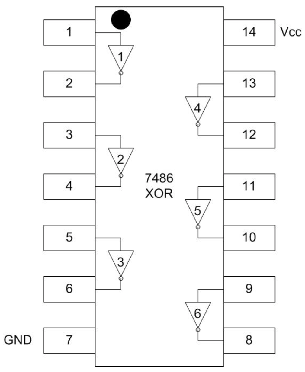
- Install and power the 7408 (AND) chip.
- Connect a wire from switch A to the first NOT gate, pin 1, on the 7404 chip. The output for this NOT gate is on pin 2
- Connect a wire from switch B to the third NOT gate, pin 5, on the 7404 chip. The output for this NOT gate is on pin 6. The third gate is used to make some separation for the wires. The second NOT gate (pin 3 input and 4 output), or indeed any two NOT gates on the chip can be used. Note that the input on pin 5 is also sent to step 8, and the output from pin 6 is sent to two separate gates in steps 6 and 7.
- Connect the two outputs from the NOT gates, pins 2 and 6 on the 7404 chip, to the third AND gate on the 7808 chip, pins 12 and 13. Connect the output from this AND gate, pin 11, to the A'B' LED. Note that the input on pin 13 is forwarded and to step 6.
- Connect switch B and the A’ output (forwarded from pin 13 in step 5), to the fourth AND gate on the 7808 chip, pins 9 and 10. Connect the output from this AND gate, pin 8, to the A'B LED.
- Connect switch A and the B' output, pin 6 on the 7404 chip, to the first AND gate on the 7408 chip, pins 1 and 2. Connect the output of this AND gate, pin 3, to the AB’ LED. Note that the A input is also connected forward to the next gate. Note that the input on pin 1 from switch A is also sent on to step 8.
- Connect switch A (from pin 1 in step 7) and switch B (from pin 5 in step 4) to the second AND gate, pins 4 and 5, on the 7408 chip. Connect the output of this AND gate, pin 6, to the AB LED. Note that the A switch input to the second AND gate is connected from the first AND gate.
Figure \(\PageIndex{2}\): Decoder circuit 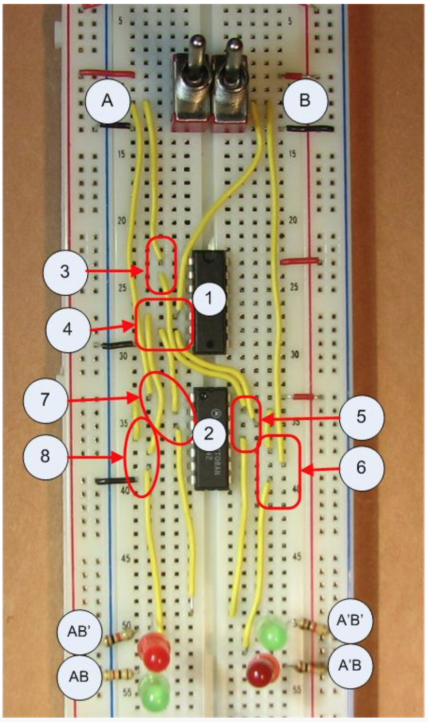
The decoder should now work. One light should come on for each of the 4 combinations of switch positions. Keep this circuit intact as it will be used in the multiplexer IC in Chapter 8.