7.4: Implementing a Decoder Using a Single Chip
- Page ID
- 26991
\( \newcommand{\vecs}[1]{\overset { \scriptstyle \rightharpoonup} {\mathbf{#1}} } \)
\( \newcommand{\vecd}[1]{\overset{-\!-\!\rightharpoonup}{\vphantom{a}\smash {#1}}} \)
\( \newcommand{\id}{\mathrm{id}}\) \( \newcommand{\Span}{\mathrm{span}}\)
( \newcommand{\kernel}{\mathrm{null}\,}\) \( \newcommand{\range}{\mathrm{range}\,}\)
\( \newcommand{\RealPart}{\mathrm{Re}}\) \( \newcommand{\ImaginaryPart}{\mathrm{Im}}\)
\( \newcommand{\Argument}{\mathrm{Arg}}\) \( \newcommand{\norm}[1]{\| #1 \|}\)
\( \newcommand{\inner}[2]{\langle #1, #2 \rangle}\)
\( \newcommand{\Span}{\mathrm{span}}\)
\( \newcommand{\id}{\mathrm{id}}\)
\( \newcommand{\Span}{\mathrm{span}}\)
\( \newcommand{\kernel}{\mathrm{null}\,}\)
\( \newcommand{\range}{\mathrm{range}\,}\)
\( \newcommand{\RealPart}{\mathrm{Re}}\)
\( \newcommand{\ImaginaryPart}{\mathrm{Im}}\)
\( \newcommand{\Argument}{\mathrm{Arg}}\)
\( \newcommand{\norm}[1]{\| #1 \|}\)
\( \newcommand{\inner}[2]{\langle #1, #2 \rangle}\)
\( \newcommand{\Span}{\mathrm{span}}\) \( \newcommand{\AA}{\unicode[.8,0]{x212B}}\)
\( \newcommand{\vectorA}[1]{\vec{#1}} % arrow\)
\( \newcommand{\vectorAt}[1]{\vec{\text{#1}}} % arrow\)
\( \newcommand{\vectorB}[1]{\overset { \scriptstyle \rightharpoonup} {\mathbf{#1}} } \)
\( \newcommand{\vectorC}[1]{\textbf{#1}} \)
\( \newcommand{\vectorD}[1]{\overrightarrow{#1}} \)
\( \newcommand{\vectorDt}[1]{\overrightarrow{\text{#1}}} \)
\( \newcommand{\vectE}[1]{\overset{-\!-\!\rightharpoonup}{\vphantom{a}\smash{\mathbf {#1}}}} \)
\( \newcommand{\vecs}[1]{\overset { \scriptstyle \rightharpoonup} {\mathbf{#1}} } \)
\( \newcommand{\vecd}[1]{\overset{-\!-\!\rightharpoonup}{\vphantom{a}\smash {#1}}} \)
\(\newcommand{\avec}{\mathbf a}\) \(\newcommand{\bvec}{\mathbf b}\) \(\newcommand{\cvec}{\mathbf c}\) \(\newcommand{\dvec}{\mathbf d}\) \(\newcommand{\dtil}{\widetilde{\mathbf d}}\) \(\newcommand{\evec}{\mathbf e}\) \(\newcommand{\fvec}{\mathbf f}\) \(\newcommand{\nvec}{\mathbf n}\) \(\newcommand{\pvec}{\mathbf p}\) \(\newcommand{\qvec}{\mathbf q}\) \(\newcommand{\svec}{\mathbf s}\) \(\newcommand{\tvec}{\mathbf t}\) \(\newcommand{\uvec}{\mathbf u}\) \(\newcommand{\vvec}{\mathbf v}\) \(\newcommand{\wvec}{\mathbf w}\) \(\newcommand{\xvec}{\mathbf x}\) \(\newcommand{\yvec}{\mathbf y}\) \(\newcommand{\zvec}{\mathbf z}\) \(\newcommand{\rvec}{\mathbf r}\) \(\newcommand{\mvec}{\mathbf m}\) \(\newcommand{\zerovec}{\mathbf 0}\) \(\newcommand{\onevec}{\mathbf 1}\) \(\newcommand{\real}{\mathbb R}\) \(\newcommand{\twovec}[2]{\left[\begin{array}{r}#1 \\ #2 \end{array}\right]}\) \(\newcommand{\ctwovec}[2]{\left[\begin{array}{c}#1 \\ #2 \end{array}\right]}\) \(\newcommand{\threevec}[3]{\left[\begin{array}{r}#1 \\ #2 \\ #3 \end{array}\right]}\) \(\newcommand{\cthreevec}[3]{\left[\begin{array}{c}#1 \\ #2 \\ #3 \end{array}\right]}\) \(\newcommand{\fourvec}[4]{\left[\begin{array}{r}#1 \\ #2 \\ #3 \\ #4 \end{array}\right]}\) \(\newcommand{\cfourvec}[4]{\left[\begin{array}{c}#1 \\ #2 \\ #3 \\ #4 \end{array}\right]}\) \(\newcommand{\fivevec}[5]{\left[\begin{array}{r}#1 \\ #2 \\ #3 \\ #4 \\ #5 \\ \end{array}\right]}\) \(\newcommand{\cfivevec}[5]{\left[\begin{array}{c}#1 \\ #2 \\ #3 \\ #4 \\ #5 \\ \end{array}\right]}\) \(\newcommand{\mattwo}[4]{\left[\begin{array}{rr}#1 \amp #2 \\ #3 \amp #4 \\ \end{array}\right]}\) \(\newcommand{\laspan}[1]{\text{Span}\{#1\}}\) \(\newcommand{\bcal}{\cal B}\) \(\newcommand{\ccal}{\cal C}\) \(\newcommand{\scal}{\cal S}\) \(\newcommand{\wcal}{\cal W}\) \(\newcommand{\ecal}{\cal E}\) \(\newcommand{\coords}[2]{\left\{#1\right\}_{#2}}\) \(\newcommand{\gray}[1]{\color{gray}{#1}}\) \(\newcommand{\lgray}[1]{\color{lightgray}{#1}}\) \(\newcommand{\rank}{\operatorname{rank}}\) \(\newcommand{\row}{\text{Row}}\) \(\newcommand{\col}{\text{Col}}\) \(\renewcommand{\row}{\text{Row}}\) \(\newcommand{\nul}{\text{Nul}}\) \(\newcommand{\var}{\text{Var}}\) \(\newcommand{\corr}{\text{corr}}\) \(\newcommand{\len}[1]{\left|#1\right|}\) \(\newcommand{\bbar}{\overline{\bvec}}\) \(\newcommand{\bhat}{\widehat{\bvec}}\) \(\newcommand{\bperp}{\bvec^\perp}\) \(\newcommand{\xhat}{\widehat{\xvec}}\) \(\newcommand{\vhat}{\widehat{\vvec}}\) \(\newcommand{\uhat}{\widehat{\uvec}}\) \(\newcommand{\what}{\widehat{\wvec}}\) \(\newcommand{\Sighat}{\widehat{\Sigma}}\) \(\newcommand{\lt}{<}\) \(\newcommand{\gt}{>}\) \(\newcommand{\amp}{&}\) \(\definecolor{fillinmathshade}{gray}{0.9}\)A decoder circuit is a commonly used IC, and so it has been implemented in an IC chip. This chip is easier to use than having to produce this entire circuit, so it will be used in chapter 9 to implement a multiplexor. This next section will cover implementing the 74139 decoder chip in a circuit.
\(\PageIndex{1}\) The 74139 chip
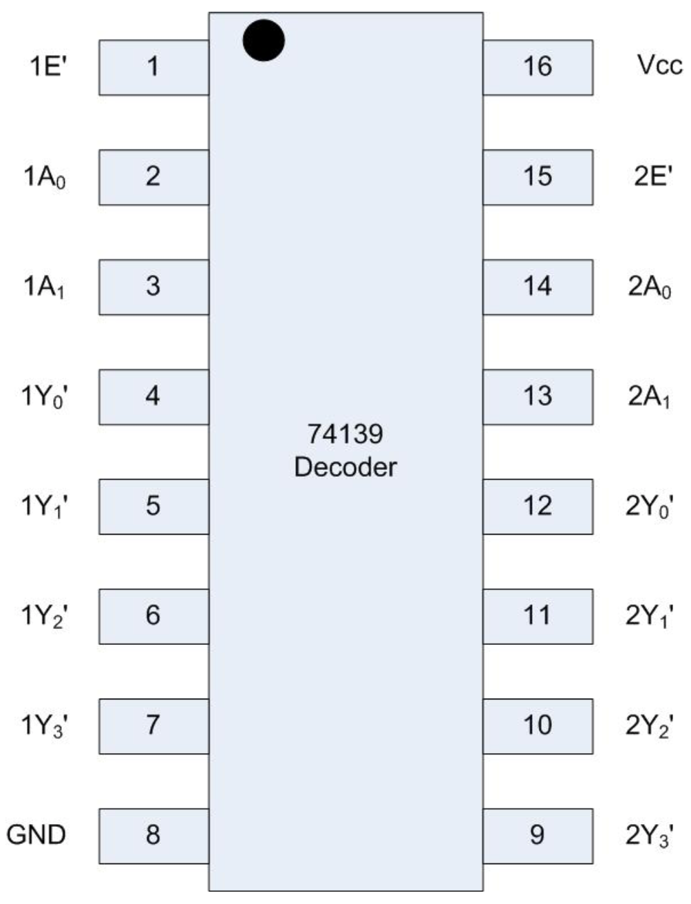
The 74139 chip implements two complete decoders implemented in a single chip. The two decoders are basically on opposite sides of the chip. The difference is that on the left side of the chip the bottom pin, pin 8, is connected to ground rail, and on the right side of the chip the top pin, pin 16, is connected to the positive rail.
The 74139 chip has an idiosyncrasy that its output is the inverse of the decoder implemented in section 8.2. This means that the selected output line is set to low, and the non-selected lines are set to high7. So to adjust for this in the implemented circuit the output will be sent to an inverter on a 7404 chip before being sent to the LEDs. This will allow the output to be as it was in section 8.2.
Figure \(\PageIndex{1}\) is the pin configuration diagram for the 74139 chip. The two decoders on the chip are numbered 1 and 2. The inputs to the first decoder are 1E', 1A0, and 1A1, and the inputs to the second decoder 2E', 2A0, and 2A1. The values of A0 and A1 are the select lines for each decoder. The E' is an enable input low bit. If E' is not enabled (E is positive or not connected), the circuit is basically disconnected, it is neither positive or ground and the results should not be used. If E' is enabled (or connected to ground), the circuit is connected. The use of enable bits is to allow power to be reduced in the circuit, and is an engineering concern, and not really of concern to the circuit.
The outputs from the decoder are labeled 1Y[0-3] and 2Y[0-3]. They are also active low, and the output line which is low is the one which is selected. In the circuit in this section, only the first decoder will be used, and the outputs will be sent to a 7404 inverted to convert the output to the more common positive output expected.
\(\PageIndex{2}\) Implementing one 2-to-4 decoder using the 74139 chip
This section will outline how to implement a 2-to-4 decoder using the 74139 decoder chip. To start, remember that the output from the 74139 is enable low, or true when the output is 0. So the output from the chip will have to be sent to a 7404 (NOT), and the circuit will consist of 2 chips. The following list of steps implements the decoder circuit using the 74139 chip.
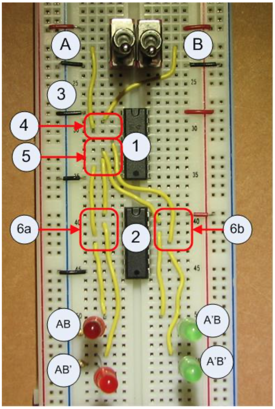
- Insert switches A and B, and the output LEDs A'B', A'B, AB', and AB.
- Insert and power the 74139 decoder chip.
- Insert and power the 7404 inverter chip.
- Enable output from the first decoder on the 74139 chip by connecting the enable low pin (pin 1) to ground.
- Connect the input switch A to pin 3 on the 74139 chip. Connect the input switch B to pin 2 on the 74139 chip.
- Connect each output 1I0 to 1I3 to an inverter input as follows:
- I0 (pin 3) on the 74139 chip is connected to the fifth inverter (pin 11) on the 7404 inverter chip.
- I1 (pin 4) on the 74139 chip is connected to the fourth inverter (pin 13) on the 7404 inverter chip.
- I2 (pin 5) on the 74139 chip is connected to the first inverter (pin 1) on the 7404 inverter chip.
- I3 (pin 6) on the 74139 chip is connected to the second inverter (pin 3) on the 7404 inverter chip.
- Connect the inverter outputs to the correct LEDs:
- Connect pin 10 on the 7404 inverter chip to the A'B' LED.
- Connect pin 12 on the 7404 inverter chip to the A'B LED.
- Connect pin 2 on the 7404 inverter chip to the AB' LED.
- Connect pin 4 on the 7404 inverter chip to the AB LED.
This circuit should now behave like the circuit in section 7.3.
7 The reason the output is set low is that the output from a decoder is often ignored unless it is the selected output. This means that positive wires can be ignored and not used. Since the low state uses less electricity and produces less heat than the high state, using a low enable rather than a high enable is an engineering decision to save power and heat.