
11.1: Introduction
- Page ID
- 25613

\( \newcommand{\vecs}[1]{\overset { \scriptstyle \rightharpoonup} {\mathbf{#1}} } \)
\( \newcommand{\vecd}[1]{\overset{-\!-\!\rightharpoonup}{\vphantom{a}\smash {#1}}} \)
\( \newcommand{\dsum}{\displaystyle\sum\limits} \)
\( \newcommand{\dint}{\displaystyle\int\limits} \)
\( \newcommand{\dlim}{\displaystyle\lim\limits} \)
\( \newcommand{\id}{\mathrm{id}}\) \( \newcommand{\Span}{\mathrm{span}}\)
( \newcommand{\kernel}{\mathrm{null}\,}\) \( \newcommand{\range}{\mathrm{range}\,}\)
\( \newcommand{\RealPart}{\mathrm{Re}}\) \( \newcommand{\ImaginaryPart}{\mathrm{Im}}\)
\( \newcommand{\Argument}{\mathrm{Arg}}\) \( \newcommand{\norm}[1]{\| #1 \|}\)
\( \newcommand{\inner}[2]{\langle #1, #2 \rangle}\)
\( \newcommand{\Span}{\mathrm{span}}\)
\( \newcommand{\id}{\mathrm{id}}\)
\( \newcommand{\Span}{\mathrm{span}}\)
\( \newcommand{\kernel}{\mathrm{null}\,}\)
\( \newcommand{\range}{\mathrm{range}\,}\)
\( \newcommand{\RealPart}{\mathrm{Re}}\)
\( \newcommand{\ImaginaryPart}{\mathrm{Im}}\)
\( \newcommand{\Argument}{\mathrm{Arg}}\)
\( \newcommand{\norm}[1]{\| #1 \|}\)
\( \newcommand{\inner}[2]{\langle #1, #2 \rangle}\)
\( \newcommand{\Span}{\mathrm{span}}\) \( \newcommand{\AA}{\unicode[.8,0]{x212B}}\)
\( \newcommand{\vectorA}[1]{\vec{#1}} % arrow\)
\( \newcommand{\vectorAt}[1]{\vec{\text{#1}}} % arrow\)
\( \newcommand{\vectorB}[1]{\overset { \scriptstyle \rightharpoonup} {\mathbf{#1}} } \)
\( \newcommand{\vectorC}[1]{\textbf{#1}} \)
\( \newcommand{\vectorD}[1]{\overrightarrow{#1}} \)
\( \newcommand{\vectorDt}[1]{\overrightarrow{\text{#1}}} \)
\( \newcommand{\vectE}[1]{\overset{-\!-\!\rightharpoonup}{\vphantom{a}\smash{\mathbf {#1}}}} \)
\( \newcommand{\vecs}[1]{\overset { \scriptstyle \rightharpoonup} {\mathbf{#1}} } \)
\(\newcommand{\longvect}{\overrightarrow}\)
\( \newcommand{\vecd}[1]{\overset{-\!-\!\rightharpoonup}{\vphantom{a}\smash {#1}}} \)
\(\newcommand{\avec}{\mathbf a}\) \(\newcommand{\bvec}{\mathbf b}\) \(\newcommand{\cvec}{\mathbf c}\) \(\newcommand{\dvec}{\mathbf d}\) \(\newcommand{\dtil}{\widetilde{\mathbf d}}\) \(\newcommand{\evec}{\mathbf e}\) \(\newcommand{\fvec}{\mathbf f}\) \(\newcommand{\nvec}{\mathbf n}\) \(\newcommand{\pvec}{\mathbf p}\) \(\newcommand{\qvec}{\mathbf q}\) \(\newcommand{\svec}{\mathbf s}\) \(\newcommand{\tvec}{\mathbf t}\) \(\newcommand{\uvec}{\mathbf u}\) \(\newcommand{\vvec}{\mathbf v}\) \(\newcommand{\wvec}{\mathbf w}\) \(\newcommand{\xvec}{\mathbf x}\) \(\newcommand{\yvec}{\mathbf y}\) \(\newcommand{\zvec}{\mathbf z}\) \(\newcommand{\rvec}{\mathbf r}\) \(\newcommand{\mvec}{\mathbf m}\) \(\newcommand{\zerovec}{\mathbf 0}\) \(\newcommand{\onevec}{\mathbf 1}\) \(\newcommand{\real}{\mathbb R}\) \(\newcommand{\twovec}[2]{\left[\begin{array}{r}#1 \\ #2 \end{array}\right]}\) \(\newcommand{\ctwovec}[2]{\left[\begin{array}{c}#1 \\ #2 \end{array}\right]}\) \(\newcommand{\threevec}[3]{\left[\begin{array}{r}#1 \\ #2 \\ #3 \end{array}\right]}\) \(\newcommand{\cthreevec}[3]{\left[\begin{array}{c}#1 \\ #2 \\ #3 \end{array}\right]}\) \(\newcommand{\fourvec}[4]{\left[\begin{array}{r}#1 \\ #2 \\ #3 \\ #4 \end{array}\right]}\) \(\newcommand{\cfourvec}[4]{\left[\begin{array}{c}#1 \\ #2 \\ #3 \\ #4 \end{array}\right]}\) \(\newcommand{\fivevec}[5]{\left[\begin{array}{r}#1 \\ #2 \\ #3 \\ #4 \\ #5 \\ \end{array}\right]}\) \(\newcommand{\cfivevec}[5]{\left[\begin{array}{c}#1 \\ #2 \\ #3 \\ #4 \\ #5 \\ \end{array}\right]}\) \(\newcommand{\mattwo}[4]{\left[\begin{array}{rr}#1 \amp #2 \\ #3 \amp #4 \\ \end{array}\right]}\) \(\newcommand{\laspan}[1]{\text{Span}\{#1\}}\) \(\newcommand{\bcal}{\cal B}\) \(\newcommand{\ccal}{\cal C}\) \(\newcommand{\scal}{\cal S}\) \(\newcommand{\wcal}{\cal W}\) \(\newcommand{\ecal}{\cal E}\) \(\newcommand{\coords}[2]{\left\{#1\right\}_{#2}}\) \(\newcommand{\gray}[1]{\color{gray}{#1}}\) \(\newcommand{\lgray}[1]{\color{lightgray}{#1}}\) \(\newcommand{\rank}{\operatorname{rank}}\) \(\newcommand{\row}{\text{Row}}\) \(\newcommand{\col}{\text{Col}}\) \(\renewcommand{\row}{\text{Row}}\) \(\newcommand{\nul}{\text{Nul}}\) \(\newcommand{\var}{\text{Var}}\) \(\newcommand{\corr}{\text{corr}}\) \(\newcommand{\len}[1]{\left|#1\right|}\) \(\newcommand{\bbar}{\overline{\bvec}}\) \(\newcommand{\bhat}{\widehat{\bvec}}\) \(\newcommand{\bperp}{\bvec^\perp}\) \(\newcommand{\xhat}{\widehat{\xvec}}\) \(\newcommand{\vhat}{\widehat{\vvec}}\) \(\newcommand{\uhat}{\widehat{\uvec}}\) \(\newcommand{\what}{\widehat{\wvec}}\) \(\newcommand{\Sighat}{\widehat{\Sigma}}\) \(\newcommand{\lt}{<}\) \(\newcommand{\gt}{>}\) \(\newcommand{\amp}{&}\) \(\definecolor{fillinmathshade}{gray}{0.9}\)Sometimes it’s nice to revisit a past project in order to investigate a different approach to the design. Here we’re going to rework the Reaction Timer exercise. While it was certainly useful as an instructional exercise, the obvious limitation as far as the game itself is concerned is the fact that the development board needed to be connected to a host PC running the Arduino software because it relied on the Serial Monitor for numeric output. Instead, we’re going to make a response timer that is self-contained. All it will need is a power source. There are a few different ways to achieve numeric output, perhaps the most direct is through the use of seven-segment LED displays. These devices will allow us to display all ten numerals plus a few alphabetic characters (but not the entire English alphabet unambiguously).
For ease of coding we shall dispense with the game “extras”, namely determining the best-of-five attempts, the average, and so forth; and instead focus on interfacing the displays to a basic response timer. The overall operation will be similar: The displays will flash quickly to tell the user to “get ready”, there will be a random time delay between one and ten seconds, then the displays will flash quickly as the trigger stimulus at which point the player will hit the response button (FSR) as quickly as possible. The response time will be shown on the displays for a few seconds and after a short pause, the process will repeat. The functional outline, or pseudo-code, is very similar to that of the original game. The major issue is the change of output device from Serial Monitor to seven-segment displays, both in hardware and software.
As far as the rest of the hardware is concerned, we will no longer need the signaling LEDs although we will still need the player’s switch (FSR). We do not expect reaction times faster than 100 milliseconds and it is doubtful that healthy individuals would exhibit response times slower than one second, assuming they are not distracted or operating within the constraints of some manner of trendy chemical amusement aid that performs a (hopefully) temporary self-inflicted misfiring of their neural network. Consequently, three displays should be sufficient, allowing us to render from 0 through 999 milliseconds.
Three displays will require 21 port bits if we drive them independently. This is about all we have on the Arduino Uno so it’s not a practical solution. Instead, we can time-multiplex the displays. In essence, we’ll render the hundreds digit on the left-most display for a few milliseconds, then render the tens digit on the middle display for a few milliseconds, and finally render the units digit on the right-most display for a few milliseconds. Then we’ll repeat the process. As long as we keep the overall loop time to less than about 25 milliseconds, our eye-brain processing will integrate the display over time so that it appears to be a solid and unwavering set of three digits. For this we’ll only need ten port bits; seven for the segments and three more to multiplex the individual displays. If we use common anode displays (e.g., FND507) we could configure them as shown in Figure \(\PageIndex{1}\).
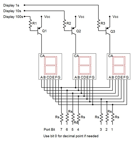
Figure \(\PageIndex{1}\): Seven-segment display configuration
The logic for this circuit will be “active low” meaning that a logic low lights a segment/display and a logic high turns it off. Note that LED drivers are not shown here, rather, the segments are connected directly to the port pins through current limiting resistors, Rs. The Arduino will have sufficient current capacity for this if we keep the segment current to a modest level. Assuming a 5 volt supply and about 2 volts for the LEDs, a 470 \(\Omega\) would keep the currents at around 6 or 7 milliamps per segment. This would be sufficient for indoor use. The individual displays are enabled through the use of the PNP drivers. A logic low on their base resistors will place them into saturation, enabling current flow to the display. For this application, a small signal PNP such as the 2N3906 will suffice. Having all segments lit will draw about 50 milliamps through the collector. Therefore, a base resistor value in the low single digit k\(\Omega\) range should work well, yielding a base current of a few milliamps.
Practically speaking, it would be easiest to dedicate port D to the segments (D.1:7, Arduino pins 1–7). This does mean that we’ll lose the ability to use the Serial Monitor (it uses D.0:1) but that shouldn’t be a problem. We can use B.0:2 (Arduino pins 8–10) for the digit multiplexers and B.3 (pin 11) for the FSR. Some #defines would be good for these. We’ll also need an array of bit patterns for the displays:
// Port B.0:2 for 7 segment mux
#define DIGIT1   0x01
#define DIGIT10  0x02
#define DIGIT100 0x04
#define DIGIT111 0x07

#define FSRMASK  0x08

unsigned char numeral[]={
   //ABCDEFG,dp
   0b00000011,   // 0
   0b10011111,   // 1
   0b00100101,   // 2
   0b00001101,   // 3
   0b10011001,
   0b01001001,
   0b01000001,
   0b00011111,
   0b00000001,
   0b00011001,   // 9
   0b11111111,   // blank
   0b01100001,   // E
   0b01110011,   // r
   0b00001001,   // g
   0b00111001    // o
};

#define LETTER_BLANK  10
#define LETTER_E      11
#define LETTER_R      12
#define LETTER_G      13
#define LETTER_O      14
#define MSG_GO        -1
#define MSG_ERR       -2
The variable numeral is an array defined using binary values. Each bit signifies a segment with the MSB being segment A (top horizontal) and the LSB being the decimal point (unused here). For example, the numeral “0” requires every segment except G (the middle horizontal bar) and the decimal point to be lit. Because our circuit is active low, we put a 0 at each bit that will be lit. We repeat this process for the remaining nine numerals. We also add a few special characters, namely blank and the letters E, r, g and o. We’ll use the first two to spell “Err” for error (what we used to call a “cheat”) and the second two to spell “go” which will take the place of the former green “go” LED. We have also defined a couple of MSG variables to be examined in a moment.
Given these definitions, let’s take a look at how the setup() function has changed. We need to change which pins are being used but we still need the seed value for random(). Note that since we are setting all bit of port D to output mode, we can just blast in 0xff instead of bitwise ORing the specific bits. It is also important that we set the mux bits (DIGIT111) of port B high. As the port D pins are also low by default, all of the displays will light up when the board is reset. This will cause a considerable current draw through the microcontroller. Setting the mux bits high ensures that everything will be off (not enabled).
void setup()
{
   // set Arduino pins 0 through 7 (port D.0:7) for output displays
   DDRD = 0xff;

   // set Arduino pins 8 through 10 (port B.0:2) for output to mux LEDs
   DDRB |= DIGIT111;

   // Displays are active low so turn them off initially
   PORTB |= DIGIT111;

   // Arduino pin 11, port B.3 for input from FSR
   DDRB &= (~FSRMASK);   // initialize the pin as an input.
   PORTB |= FSRMASK;     // enable pull-up

   // get seed value for random- noise voltage at pin A0
   randomSeed(analogRead( 0 ));
}
Here is our main loop, slightly altered. Compare it line-by-line to the original version and note any similarities and alterations. The comments alone should provide sufficient detail. The most obvious changes are the removal of the Serial Monitor code and the inclusion of a new function called DisplayValue() which will be discussed shortly.
void loop()
{
   unsigned long starttime, finishtime;
   int i, j, nettime;
   long a;

   for(i=0;i<5;i++)
   {
      a = random(1000, 10000);

      // wait a couple of seconds to start this round
      delay(2000);

      // flash display a few times to tell player to get ready
      for(j=0;j<5;j++)
      {
         DisplayValue( 888, 100 );
         delay(100);
      }

      // delay random amount
      delay(a);

      // flash LED for real
      starttime = millis();
      DisplayValue( MSG_GO, 50 );

      // wait for response, pressing FSR makes a low
      while( PINB & FSRMASK );

      finishtime = millis();
      nettime = finishtime - starttime;

      // check for cheat
      if( nettime < 100 )
         nettime = MSG_ERR;

      DisplayValue( nettime, 3000 );
   }
}
Functionally, DisplayValue() is fairly straight-forward to use. The first argument is the number to be displayed, from 0 through 999. The second value is the duration of the display in milliseconds. So DisplayValue( 888, 100 ) means “display the number 888 for 100 milliseconds”. This particular line makes the “get ready” flash. DisplayValue() also allows for a few special values. These are encoded as negative values. A negative response time is impossible, of course, without some form of time travel ability. If the value is set to MSG_ERR then the display shows “Err”. If the value is set to MSG_GO then the display shows “go”. Thus the former flashing of the green “go” LED is replaced with DisplayValue( MSG_GO, 50 ), producing the “go” message for 50 milliseconds.
The first thing the function should do is validate the value passed to it. It needs to check for the special message codes as well as values out of range. Whatever value is passed, we must derive three new values, namely the indices for the numeral array. These will be stored in the variables h, t and u which stand for hundreds place, tens place and units place. The special cases should be checked first. Beyond that the value needs to be broken down into its individual digits through the use of integer divides and mods. Successive integer divisions by 10 will effectively shift the number down a place while mod by 10 will leave the remainder. Think of a three digit number at random and verify that the logic works.
void DisplayValue( int v, int msec )
{
   unsigned char i, h, t, u;

   if( (v <= MSG_ERR) || (v > 999) ) // error code
   {
      h = LETTER_E;
      t = u = LETTER_R;
   }
   else
   {
      if( v == MSG_GO )
      {
         h = LETTER_G;
         t = LETTER_O;
         u = LETTER_BLANK;
      }
      else
      {
         u = v%10;
         v = v/10;
         t = v%10;
         h = v/10;
      }
   }
At this point we need to turn the requested duration into loop iterations. As coded, each iteration lasts about 15 milliseconds given that each digit is illuminated for 5 milliseconds. A simple division will suffice although we may wish to guard against someone accidentally requesting just a few milliseconds (which would yield zero).
   // turn millisecs into loop iterations
   msec = msec/15;
   if( msec < 1 )
      msec = 1;
We now create a loop that will roughly yield the requested duration with 15 millisecond resolution. Inside the loop, first we clear all of the displays. Then we enable the desired display and blast in the code for the numeral. Note that by entering the binary values into the array in ascending order we can just use the computed digit value as the index into the array. We don’t need to translate the desired numeral into the appropriate index. A little forethought can save coding effort and memory space. Each digit is held for 5 milliseconds. At the close of the function we turn off the display.
   // display the value for the specified time
   for( i=0; i<msec; i++ )
   {
      // clear all displays then activate the desired digit
      PORTB |= DIGIT111;
      PORTD = numeral[h];
      PORTB &= ~DIGIT100;
      delay(5);

      PORTB |= DIGIT111;
      PORTD = numeral[t];
      PORTB &= ~DIGIT10;
      delay(5);

      PORTB |= DIGIT111;
      PORTD = numeral[u];
      PORTB &= ~DIGIT1;
      delay(5);
   }

   // clear display
   PORTB |= DIGIT111;