
12.1: Introduction
- Page ID
- 25620

In this exercise we shall examine analog output through the use of PWM or pulse width modulation. PWM is a method to produce analog signals using a digital output rather than a true continuously variable output. While some microcontrollers and boards have true DACs built-in (the Arduino Due being one example), most do not. Therefore, a digital pulse output is used with a variable duty cycle. The “analog” signal basically is the “area under the curve”. If you thought of averaging the pulse train with a low pass filter, a small duty cycle would achieve a low value and a high duty cycle would achieve a high value. Some loads may need proper filtering of the pulse train but some do not. In this exercise we shall begin by examining a simple LED.
It is easy enough to flash an LED on and off. Consider the code below:
/* PWM V1 Manual LED brightness test */

#define LEDBIT   0x40

// on/off time in msec
#define LEDONTIME   300
#define LEDOFFTIME  300

void setup()
{
      // set Arduino pin 6 for output to an LED
      DDRD |= LEDBIT;
}

void loop()
{
      PORTD |= LEDBIT;    // turn on LED
      delay(LEDONTIME);

      PORTD &= (~LEDBIT); // turn off LED
      delay(LEDOFFTIME);
}
In this example the LED flashes on and off 300 milliseconds each for a total cycle time of 600 milliseconds. Attach a standard NPN LED driver circuit to power, ground and Arduino pin 6. Enter the code, compile, transfer and run it to verify. Reduce the on/off times to 30 milliseconds each and repeat. The LED should flash much faster. Reduce the on/off times to 5 milliseconds each and repeat. A curious thing happens. The LED doesn’t seem to be flashing anymore; rather it just seems dimmer. Once the timing drops below about 20 milliseconds, the human eye integrates the visual input over time and we no longer see discrete flashes1. Instead, we see the average illumination. Since the LED is only on for half the total time, it appears dimmer than a single long flash. You can verify this by changing the on time to 1 millisecond and the off time to 9 milliseconds, still achieving a 10 millisecond cycle time. The LED should appear quite dim as the average level is now only 10 percent of the maximum.
Instead of adjusting the timing manually, we can use the library function analogWrite() on one of the PWM capable output pins (these are marked with a “~” next to the header). Fortunately, pin 6 is PWM capable so all we need is a little change to the code:
/* PWM V2 LED brightness using analogWrite */

#define LEDPIN 6

// brightness 0 to 255
#define LEDBRIGHTNESS 230

void setup()
{
}

void loop()
{
      analogWrite(LEDPIN,LEDBRIGHTNESS);
}
Note that pin 6 does not need to be set for output mode as this is done automatically by the analogWrite() function (see “Bits & Pieces: analogWrite” in the text for details). If you placed an oscilloscope at pin 6 you’d see a square wave at about 490 Hz with 90 percent duty cycle. Note that the LEDBRIGHTESS parameter can be replaced with the results from an analogRead() call. So, we can connect a potentiometer to an analog input pin and read its voltage which will range from 0 to 1023. We then scale this range onto the 0 to 255 (unsigned char) input of analogWrite() to create a dimmer. The scaling can be performed using the Arduino library function map(). The template is:
result = map(value, fromLow, fromHigh, toLow, toHigh);
In our case we’d use:
result = map(value, 0, 1023, 0, 255);
To continue, wire a 10 k\(\Omega\) potentiometer between power and ground, connecting the wiper arm to Arduino pin A0. Enter the code below, compile and transfer it.
/* PWM V3 LED dimmer using analogWrite and potentiometer */

#define ANALOG_IN_PIN 0
#define LEDPIN 6

void setup()
{
      analogReference( DEFAULT );
}

void loop()
{
      int a;

      a = analogRead( ANALOG_IN_PIN );

      a = map(a,0,1023,0,255);
      analogWrite(LEDPIN,a);
}
LEDs are all well and good but we might wish to control something a little more interesting such as a motor. Obviously, our LED driver circuit will be insufficient for any decently sized motor but it will do just fine for a small 10–15 milliamp (unloaded) DC hobby motor given some minor modifications. An example is seen in Figure \(\PageIndex{1}\).
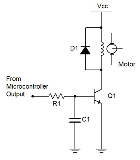
Figure \(\PageIndex{1}\): Motor controller with BJT
First note that a higher supply is required. In this case, 15 VDC would be appropriate. R1 would need to be about 6.8 k\(\Omega\) to guarantee transistor turn-on and C1 needs to be about 100 nF. D1 should be a 1N4002 rectifier. It is used to prevent, or snub, a sudden voltage spike caused by the motor’s inductance when the transistor switches state between saturation and cutoff2. For a larger load, a power FET can be used as shown in Figure \(\PageIndex{2}\). A nice load for this variation would be a common 12 volt boxer fan (of one or two watts dissipation). The ZVN4206A EMOSFET would be a decent choice for this larger load as it handles 600 milliamps continuous and 8 amps pulsed (set Vdd to 12 VDC).
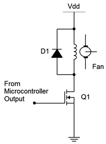
Figure \(\PageIndex{2}\): Fan controller with EMOSFET
Build one of the control circuits and connect it to Arduino pin 6 in place of the LED driver. (You might want to keep the LED driver wired up for upcoming modifications and additions.) There is no need to change the code. Once the motor circuit is connected, its speed should now be controlled by the potentiometer.
References
1If this was not the case we would not get the impression of continuous motion while watching TV or movies which use frame rates of 30 and 24 frames per second respectively. The frames “blur together” in our brains creating the illusion of continuous motion.
2Remember, the current through an inductor cannot change instantaneously. The sudden transistor switching would result in a large inductor reverse voltage which would in turn cause a large voltage spike across the transistor due to KVL. So the diode is placed there to limit said voltage and protect the devices. See: http://en.Wikipedia.org/wiki/Flyback_diode